
Vishal Jadhav1, Yizheng Zhou2
1Infineon Technologies India Pvt Ltd, 7th Floor, Navigator Building, ITPB, Whitefield road, Bangalore 560 066, India.
2Infineon Technologies China Co. Ltd, No. 7&8, Lane 647, Zhangjiang Hi-Tech Park, Shanghai 201203, P.R. China.
Abstract
Achieving symmetrical dynamic current sharing of high power IGBT’s in parallel has always been the concern for IGBT converter designers. In this paper various measurement results are presented on the external components associated with the IGBT module which influences the current sharing of the paralleled IGBT modules. Experimental results showing current sharing of paralleled IGBT’s under single gate driver operation, results under multiple gate driver operation, results with different gate cable lengths for IGBT driving. Different mechanical setup of the DC/AC busbar’s are made to show the effect of the unsymmetrical/symmetrical commutation loop resistance & inductance on current sharing in paralleled IGBT modules .The results conclude that the commutation link inductance and resistance due to the DC/AC busbar connection dominates the dynamic current sharing of IGBT modules in parallel.
1. Introduction:
Today’s application segments like Wind, Traction, AC Drives etc have already reached several Megawatt of power range. With increase of converter rating in these applications from few hundred’s of KW upto MW range has triggered the need of high current IGBT module. Designers of such high power converter predominantly have only two choices, one to use a single IGBT module of very high current rating for the inverter design or to use several high-medium current half bridge IGBT modules in parallel to achieve the desired current level. In order to cope up with the application demand, IGBT’s were developed upto a current range of 3600A in single switch configuration, but even this current rating was insufficient to fullfill the application demand. Also using single IGBT module to build half bridge will induce big communication stray inductance, as AC connection is hard to be done perfectly. The further development of high current IGBT’s currently faces challenges such as the limitation on chip dimension per die, module housing, module stray inductance and many more. Due to the flexibility in the thermal design, cost, easy availability of module, positive temperature coefficient Vcesat, high power gate drivers etc facilitated the more and more use of IGBT’s in parallel instead of designs with single high current IGBT module.
Due to the different static & dynamic characteristics of IGBT chips, paralleling of modules results in unequal static & dynamic current sharing. A derating factor has to be taken in to account in order to take care of unequal current sharing. This results into an overrated design rather than an optimized one. Today the IGBT chip manufacturers are able to achieve very close distribution of Vcesat among the IGBT chips, the new module packages are made available with high degree of symmetry in the layout of paralleled chips, the stray inductance in the module also have been significantly reduce and are symmetrically distributed hence the factor which predominately determine the equal current sharing between the modules has shifted from inside the module to outside the module. Factors like gate drivers, gate emitter cable lengths and different commutation loop resistance and the inductance introduced by the DC/AC busbar connection topics are focused in this paper.
1.1. Experimental setup:
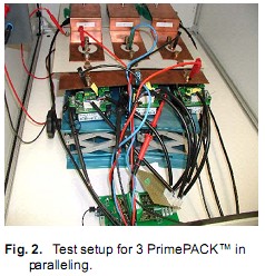
The dynamic current sharing tests are carried out in the double pulse test setup used for characterization of IGBT and Diode parameters. The latest PrimePACKTM module FF1000R17IE4 of 1000A/1700V E4 chip is under test. 3 modules of FF1000R17IE4 are in parallel to study the dynamic and static current sharing of the module under various conditions. The basic schematic of double pulse test setup is shown in Fig 1, the bottom IGBT in the diagram is subjected to double pulse test. Fig 2 shows the test setup of 3 paralleled FF1000R17IE4 modules under test.
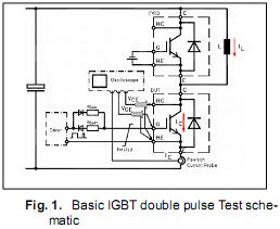
The setup was intentionally made crude and the gate cable and load cable were haphazardly arranged in order to achieve worst case scenario. For all the experiment expect section 2.1 and 2.2 the DC/AC bus connection are symmetrical.
2.1 Influence of single gate driver on IGBT current sharing:
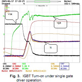
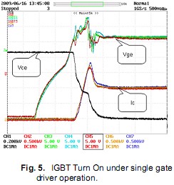
The gate charge requirement of the gate driver increases with increase in number of modules in parallel. Different gate driver have different propagation delay due to which the possibility of different switching speed cannot be ignored. Most of the converter designers prefer to use a single gate driver to driver the paralleled IGBT modules due to this reasons. The experimental waveform in Fig 3 conducted with unsymmetrical AC/DC bus bar and single gate driver shows the dynamic current sharing of paralleled IGBT. The turn-on behaviour of the IGBT shows a magni-tude of current mismatch of the order of 10%. The mismatch is predominately the during the current peak caused by the reverse recovery of the freewheeling diode. Due to the transfer char-acteristics of the IGBT gate voltage exceed the Miller plateau voltage in the same ratio like the current exceeds the static value of Icnom.
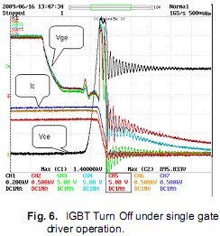
Irrespective of the same switching gate pattern delivered by the single gate driver the Turn-off operation of the paralleled IGBT’s also shows the imbalance in the current in the order of app.10% to 15%. Ignoring the static current sharing, which is mainly caused by unsymmetrical bus bar, turning off shows coupling of gate which leads to current coupling during Vce raising period?
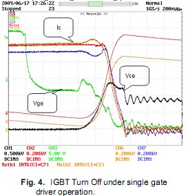
Even though the paralleled IGBT’s are driven by a single gate driver in order to avoid propagation delays in switching, the dynamic current sharing still could not be 100% achieved.
2.2 Influence of multiple gate driver on IGBT current sharing:
Due to the output current and power limitation in the availability of high power gate drivers, most of the designers implement multiple gate drivers in the converter design to switch parallel IGBT’s. The major concern in this design is the different propagation delays in gate driver electronics re-sulting into different switching signal to different IGBT modules. The experiments were carried out on an unsymmetrical AC/DC busbar with multiple gate drivers to switch the parallel IGBT modules.
Waveform in Fig.5. Shows similar turn on behaviour of the IGBT as that of during single gate driver operation.
The waveform of IGBT turn Off during multiple gate drive operation showed a huge mismatch of the order of 300Amps between Module 3 and Module 1.Such behaviour can be expected be-cause of the different propagation delay of gate drivers and decoupling of each gate signal.
Test concludes that different drivers with different propagation delay will lead to higher magnitude of current missharing under unsymmetrical AC/DC busbar and different gate driver.
2.3 Influence of Saturation voltage on IGBT current sharing:
The new generation IGBT’s are having very close distribution of Vcesat. Change in Vcesat been a function of junction temperature [Tvj], Gate Emitter voltage [Vge] and Collector current [Ic] therefore is predominantly a static parameter hence its effect on dynamic current is minimal.
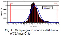
Experiment was conducted to experience the in-fluence of Vcesat on dynamic current sharing. Module with different Vcesat were selected and introduced in the setup with Symmetrical AC/DC connections.
The Turn on behaviour of the module is shown in Fig. 8 and the Turn off behaviour is shown in Fig. 9 In both the switching events the current mis-match is very less and is comparable to modules with same Vcesat.
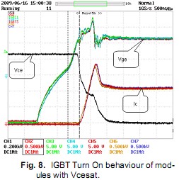
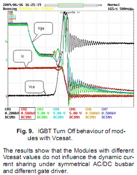
The results show that the Modules with different Vcesat values do not influence the dynamic current sharing under symmetrical AC/DC busbar and different gate driver.
2.4 Influence of Symmetrical commu-tation loop inductance on IGBT current sharing:
The asymmetrical commutation stray induct-ances for paralleled IGBT’s will result in dynamic current imbalance in the whole power circuit these results to different switching speeds. If the equivalent stray inductance of one branch is higher compaired to other modules then the switching-on power losses are relatively low but the adverse effect is the higher overvoltage during IGBT turn-off.
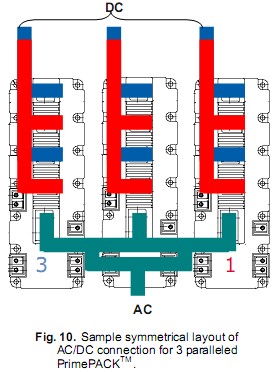
During IGBT fast switching process, the collector current will induce voltage by internal stray in-ductance. The voltages are counteractive to gate charging or discharging respectively by negative feedback. The consequent deceleration of switching process will increase the power losses. Values of that inductance might contribute to asymmetric distribution of power losses and current flow. Fig. 10 shows a symmetrical connection of 3 paralleled IGBT modules. The AC busbar is constructed in such a way to have similar inductances & resistances for all the 3 parallelmodules. Similar construction is also assumed of the DC section.
In the previous section 2.2 we have seen that paralleling with different gate drivers under un-symmetrical AC/DC busbar results in very high current imbalance of an order of 30% app. Similar measurement were carried out with symmetrical AC/DC busbar connections and multiple gate drivers.
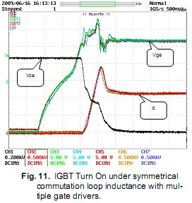
Fig 11 show the turn on behavior of the paralleled IGBT’s under symmetrical AC/DC connection and multiple gate driver operation. In spite of different switching event from different gate drivers the current mismatch during turn-on stage is almost negligible.
Similarly the Turn Off event as shown in Fig 12 shows a perfect balance between the output current in parallel operation.
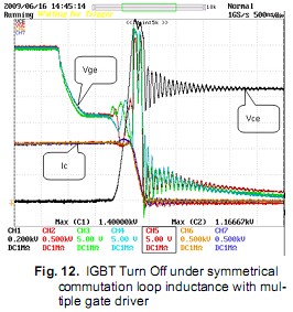
The above test provides strong evidence that the symmetry of the commutation loop dominates all the other parameters influencing the paralleling in IGBT modules.
2.5 Influence of Symmetrical commutation loop inductance on IGBT current sharing with multiple drivers and different gate emitter cable length:
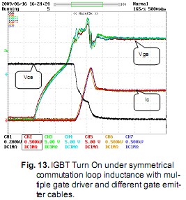
To ensure that the symmetry of the commutation loop dominates all other parameters influencing the current sharing in parallel module, another test was carried out with multiple gate drivers with different gate emitter cable inductance. The3 paralleled PrimePACKTM modules were driven with 3 different lengths of gate cable of 8mm, 29mm and 60mm to achieve different switching speeds.
Fig 13 shows the turn on behaviour of the paralleled IGBT’s under symmetrical AC/DC connection and multiple gate driver operation with different gate emitter cable lengths. In spite of different switching speeds from the different gate emitter cables and different gate drivers the current sharing is almost similar.
Similarly the turn off event shown below is in perfectly balanced state.

The above test concludes that the symmetry of the commutation loop dominates all the other parameters influencing the paralleling in IGBT modules. Hence a lot of design effort has to be directed in designing a symmetrical DC/AC busbar connection for achieving dynamic and static current sharing in the parallel IGBT modules.
2.6 Conclusion:
The dynamic current sharing in paralleled IGBT is possible with out the special selection of IGBT’s with same internal parameters. The low propagation delay in gate driver strategy enhances the current balance in the parallel IGBT’s and is equally important. But the most important parameter which cannot be neglected in order to achieve perfect dynamic as well as static current balance in parallel module is the symmetry of the mechanical layout. The symmetry includes the symmetry of both DC and AC section. This symmetry in the AC/DC busbar will not only help in achieving perfect current balance but also will help to reduce the switching losses. An excellent mechanical design is therefore needed to take care of symmetry and also the stray inductance so as to achieve an optimised converter design.
3. Literature
[1] Andreas Volke, Vishal Jadhav. Infineon Technologies. Power switching device strategies for driving IGBT power modules: National Power Electronics Conference 2007,India
[2] Zhao Zhenbo, Infineon Technologies. Design reference on IGBT paralleling, Application note Oct 2007.