
Integrated Magnetic Components for Current Doubler Rectifier and Analogous Circuits Using Bobbin less U Cores
H. Njiende, R. Robrecht, P. Ide
Delta Energy Systems GmbH, Coesterweg 45, 59494 Soest, Germany
Tel.: +49 2921 987 472 Fax.: +49 2921 987 416
Email: hugues.njiende@delta-es.com
Abstract
Switched mode power supplies as main part of telecom and commercial systems often dictate their size and electrical performance as well as reliability and costs. As requirements for the key characteristics power density and efficiency of power converters increase, the demands of these evaluation characteristics increase for inductive components particularly. One powerful approach of increasing the power density and the efficiency is to integrate the inductive components. Transformers and inductors can be integrated into a single magnetic structure which than reduces cost, increases power density and power efficiency. Several published works on current- doubler rectifiers with integrated magnetic components are known, which are all based on EE cores with bobbin [1], [2], [3],[4], [5] and [6]. One additional approach of increasing the power density and the efficiency is the use of bobbin less cores. This paper presents new integrated magnetic structure composed of bobbin less U cores which are used as flexible building blocks. The core structure can either be fully composed of high permeability low saturation cores with air gaps or be composite comprising low permeability high saturation cores and high permeability low saturation cores with no air gaps. The operation and performance of the magnetic structure is verified on a 1KW, 400 V input 12V output Full-bridge converter.
1. Introduction
The current- doubler rectifier circuit, habitually applied for low voltage and high current outputs, is used with different double-ended primary topologies such as forward, two transistors- forward, push-pull, half bridge or full bridge inverters and uses one simple two- winding transformer and two output inductors (Fig.1 a). The current- doubler rectifier then exhibits lower conduction losses than the conventional center tapped rectifier. This configuration results, additionally to the number of discrete magnetic components which yield higher size and costs, in three high current windings and several high interconnection losses which negatively impact the efficiency. Consequently integrated magnetics are strongly recommended for this circuit to solve the listed problems. Several published works on current- doubler rectifiers with integrated magnetic components are known which are all based on EE cores with bobbin [1], [2] and [3].Resulting structure from [3] is depicted in Fig.2 b. Although these core forms are very popular and widely-used they lack flexibility for integrated magnetics. Moreover the bobbins lead to more leakage inductances and copper losses.
In the present work new bobbin less U cores are used on whose legs the windings are directly wound.The tight core- winding coupling yields lower leakage, minimized copper power losses and inductance losses as well as minimized overall thermal resistance. The U cores are used as building blocks which make their mechanical and magnetic (for ex. different materials) assembly more flexible. The core structure can either be fully composed of high permeability low saturation cores with air gaps or be composite comprising low permeability cores and high permeability cores with no air gaps.
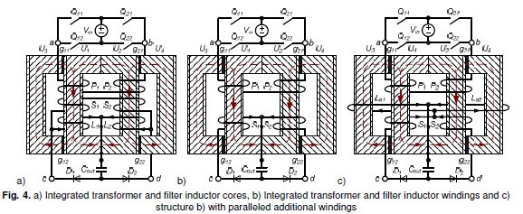
A synthesis of the integration of cores and windings and the analysis of each integration step is performed. Beginning with discrete transformer and output filter inductors, the later are coupled properly to provide inverse coupling Fig. 2 a. Further the transformer and the coupled output inductors are integrated into a single structure, Fig.4 a. The transformer cores and secondary windings are removed without substantially altering the converter functionality, Fig.4 a and b. In order to achieve a reasonable value (1.35uH) of filter inductance without saturation of inner or outer core legs, additional filter windings (1 turn) are inserted and wound in parallel around outer core legs as illustrated in Fig.4 c.

The operation and performance of the final magnetic structure as well as its analysis is verified on a 1KW, 400 V input 12V output Full-bridge converter. Experiments results are presented in section 3.
2. From discrete magnetics to new integrated magnetics
The current- doubler rectifier, habitually applied for low voltage and high current outputs, is used with a full bridge inverter and comprises one simple two- winding transformer and two output inductors, (Fig.1 a). This converter circuit results, additionally to the number of discrete magnetic components, which yield higher size and costs, in three high current windings and several high interconnection losses which negatively impact the efficiency. The integrated magnetics technique constitutes an important tool in order to reduce the number of components and therefore the number of interconnections which results in lower winding and interconnection losses as well as lower material costs. Additionally the bobbin less technique is applied to furthermore reduce the winding losses through shortened mean turn length of winding and reduce leakage inductances through a tight coupling between windings and cores. Both techniques are combined to a powerful instrument for building of flexible, high density, high efficiency, and low cost magnetic component assembly.
Using the bobbin less U cores the discrete magnetic components are built. The primary and secondary windings of the transformer are split and each half winding wound around a core leg tightly (P1 and S1 on U1 as well as P2 and S2 on U2) in order to reduce proximity losses. The increase of coupled capacitance between windings and core is the only setback resulting from the tight coupling. For purpose of illustration the inductor windings are wound around just one core leg (L1 on U5 as well as L2 and U6) which is jointed to another core through distributed air gaps (g11 and g12 or g21 and g12). The distributed air gaps lead to reduction of arc of fringing fields which therefore result to a decrease of negative effects on nearby windings and components. In addition, contrarily to widely used EE cores, the air gaps are not perpendicular to the windings, which results in reduced fringing field losses [8]. Actually the air gap fringing field slightly affect just the end turns of the windings.
Adding to cited setbacks, the number of components and of high current interconnections, the current-doubler rectifier exhibits additional limitations. In order to reduce output ripple voltage the ripple currents of the inductors are reduced by increasing their inductances which implies more copper losses. On the other hand in order to allow a fast transient response during change in power requirements, the inductances need to be small. High efficiency and fast transient response requirements are conflicting regarding the design of the inductors [4], [5], [6] and [7]. Coupled inductors are suitable to achieve both requirements simultaneously.
2.1. Coupled output inductors
The first integration step is the coupling of both output inductors whereby the coupling is either direct or inverse [5], depending on the winding direction of inductor windings L1 und L2, Fig. 2 a
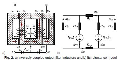
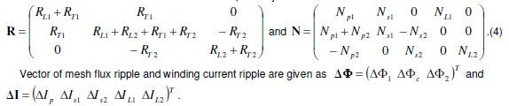
Applying Kirchhoff’ voltage Law on the reluctance model in Fig. 2 b, next matrix equation is defined R ⋅ Φ = N ⋅ I
with R and N .being reluctance and turn number matrices respectively. Vector of mesh fluxes and winding currents are as  winding currents are as

LHand M are the self- and mutual inductances respectively. Due to symmetrical buildup of the structure it can be assumed: N?1=N?2=N? and R?1=R?2=R? The mutual inductance is negative for inverse coupling ( Msign = −1) and positive for direct coupling Msign = +1.
High efficiency is achieved during steady state and fast response is realized during transient modus with inverse coupling, [5]. Contrarily, the direct coupling implies lower equivalent inductances in the steady state intervals which will worsen the efficiency.
In the following inversely coupled inductors are analyzed closely. Current and flux ripples of each state interval, summarized in Table 1 are calculated using following equations, with the scalar ∆T being time of each interval and V = (uL1uL2)T the vector of voltage on windings during each interval

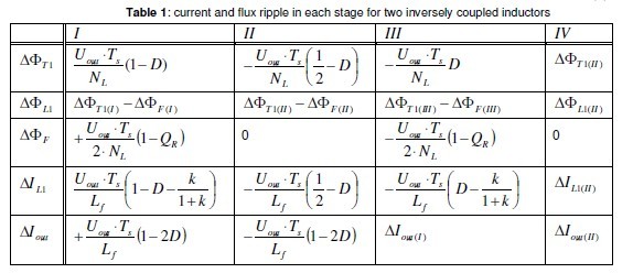
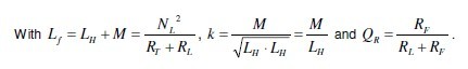
Fig. 3. a) Winding current waveforms and b) core flux waveforms of the proposed structure in Fig. 2 a) Calculated ripples in Table 1 are used to plot current and flux waveforms, illustrated in Fig. 3 a and b, which strongly depend on the coupling coefficients k and QR, respectively. For uncoupled windings air gap in flanges between wounded core legs is large therefore QR→ 1 and k → 0 prevail. iL1 and iL2 are 180° phase shifted. Minimum current and flux ripples are achieved for minimum flange air gaps which means RL>> RF and RL>> RT and therefore QR→ 0 and k → 1 . For theoretically zero air gap between wounded core legs iL1 and iL2 are in phase as well as ÖL1 and ÖL2.
2.2. Integrated transformer and output inductors
Though the windings have been coupled the number of core is still too high, 6 U cores. In other to reduce the volume, transformer and inductor cores are integrated in the next step. Transformer primary and secondary windings are split and each primary and secondary half winding are tightly wound around a core with either of inductor windings as depicted in Fig. 4 a. P1, S1, and L1 are wound tightly around one core leg and P2, S2, and L2 as well around the other core leg. Current waveforms of primary and secondary transformer are similar and this structure still operates as current doubler rectifier with coupled inductors. This structure simultaneously transforms and stores energy: Energy is partly transformed in the cores U1 and U2 while partly stored in gapped cores U3 andU4.
he secondary winding is obsolete and can be removed without drastically altering the functionally of the integrated structure. This action yields the next integrated structure depicted in Fig. 4 b. Additionally to preceding core integration a winding integration is achieved. Now, contrarily to previous structures, the secondary windings S1 and S2 transform and store energy. Either, current and flux waveforms are different to those of previous structures: when diode D1 conducts and diode D2 blocks, the secondary winding S1 stores energy and secondary winding S2 is without current. The current and flux waveforms,shown in Fig. 5 a and b, are now similar to those of center tapped rectifier. Still, as with the previous
integrated structure, cores U1 and U2 transform energy and gapped cores U3 andU4 store energy. For low voltage and high current outputs, for which the current doubler rectifier is optimal, it is necessary for lowering copper losses at full load to have lowest turn number at secondary windings. Since the secondary turn number also account for the filter inductor, the filtering inductance is not sufficient to achieved low current ripples. A remedy to this setback is utilization of additional filtering inductance as in [3]. Additional filter winding are wound around outer core leg as depicted in Fig. 4 c.Output current is distributed between paralleled additional windings La1 and La2 . Compared to the structure in [Sun], the current distribution generates temperature and manufacturing advantages: the heat dissipation is better and same conductor is used for all four secondary windings S1, S2, La1 and La2.
In summary the additional windings cause in one hand a drastic increase of the resulting output filtering inductance Lfa which implies reduced ripple output current and minimized conduction and switching losses. On the other hand these windings enable a reduction of ripple fluxes which signifies minimized cores losses. Although the air gaps are distributed, their inherited fringing fields still cause winding power losses and inductance losses. Moreover, to assure mechanical stability a non permeable material is inserted at location of air gap. The mounting of this material negatively affects the bonding or gluing of the cores as well as the costs. As a solution to these hindrances, low permeability high saturation bobbins less U cores are proposed to replace the outer cores, U3 and U4, of the proposed integrated magnetic structures.In the following the integrated structure in Fig. 4 c is analyzed closely including description of functionality, calculation of different current and flux ripples as well as of current and flux waveforms. With reluctance and turn number matrices respectively as
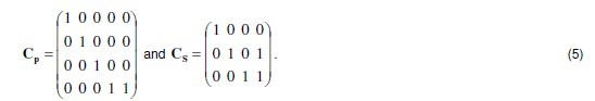
Using the connection matrix concept as explained in [9], following connections matrices, CPfor paralleling both additional windings and CS for putting each secondary winding in series with paralleled additional windings, are generated
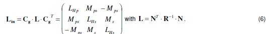
For the sake of brevity elements of inductance matrix Lin are not outlined in this paper.
Current and flux ripples of each state interval, summarized in Table 2 are calculated using following equations, with the scalar ∆T being time of each interval and V = (upus1us2)T the vector of voltage on windings during each interval.

The singularity of inductance matrix Lin is taken into account by removing the current less winding in each phase interval and inversing instead a 2 winding inductance matrix. The equivalent inductance in freewheeling phases II and IV is calculated as
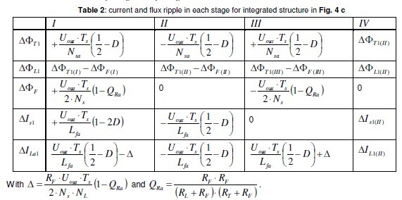
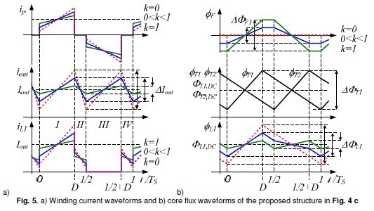
Calculated ripples in Table 2 are used to plot current and flux waveforms, illustrated in Fig. 5 a and b. The waveforms are without consideration of parasitics (i.e. coupling capacitances) and strongly depend on the coupling coefficients QRa which in turn is related to k . Minimum current and flux ripples are achieved for minimum flange air gaps which means RL>> RF and RL>> RT and therefore and k- 1 . Winding currents is1 and is2 are in 180° phase shifted as well as core fluxes ÖL1 and ÖL2, ÖT1 and ÖT2 . For theoretically zero air gap length between wounded core legs, fluxes ÖL1 and ÖL2 are in phase. Core fluxes ÖT1 and ÖT2 are independent of coupling factor QRa.
3. Experimental results
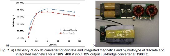
The operation and performance of the magnetic structures is verified on same 1KW, 400 V input 12V output Full-bridge converter at around 130kHz. The discrete transformer as well as the integrated structure was built using bobbin less U cores. Koolmu toroid cores were used for the discrete output inductors. The volume of magnetics is reduced by circa 25% when magnetic component integration is implemented, Fig.7 b, which signifies a reduction of overall power density.
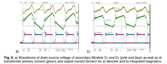
Fig. 6. a) Waveforms of drain source voltage of secondary Mosfets D1 and D2 (pink and blue) as well as of transformer primary current (green) and output current (brown) for a) discrete and b) integrated magnetics. Experiments carried out provide the waveforms of drain source voltage of secondary Mosfets (D1 , D2),of transformer primary current and output current for discrete components Fig.6 a, as well as for integrated components Fig.6 b. Output current ripple is lower for integrated magnetics due mainly to additional filter windings wound around outer legs of structure in Fig.4 c. Due to higher coupling coefficient k the transformer primary current is reduced with the magnetics integrated although the transformer and the power path are unchanged for both discrete and integrated structures. The measured reduction of current ripples validates the waveforms illustrated in Fig.5 a. The measured primary current is different during freewheeling phases, II and IV , due to parasitics not considered in Fig.5 a.
Measured efficiency of discrete and integrated magnetics is shown in Fig. 7 a. Efficiency of the dc- dc converter with integrated magnetics is at low load 1.9% higher than with the discrete components. At heavy load the efficiency of integrated magnetics is 2.6% higher. The higher copper losses of output inductors for discrete magnetics and longer onnection path mainly caused the higher discrepancy in efficiency at heavy load.
4. Conclusion
This paper presented new integrated magnetic structures, consisting of bobbin less U cores used as building blocks, for current-doubler rectifiers and analogous circuits. Beginning with the coupling of output inductors to generation of fully integrated transformers and inductors, several integrated magnetic structures are presented and analyzed. The coupling of coupled inductors is analyzed and an optimal structure of inversely coupled inductors presented and discussed. Additional windings are implemented in order to increase filtering inductance and their effect analyzed. The core structure is either fully composed of high permeability low saturation U cores with air gaps or is composite consisting of high permeability cores (ferrite) and low permeability U cores (iron powder) with no air gaps to avoid negative effect of fringing fields. Current and flux ripple formulas are deduced to facilitate analysis and design of presented integrated magnetic structures. The operation and performance of the final magnetic structure is verified on a 1KW, 400 V input 12V output Full-bridge converter. Presented experiments results demonstrated the efficiency improvement.
5. Literature
[1] Pietkiewicz, A.; Tollik, D.: Coupled-Inductor Current-Doubler Topology in Phase-Shifted Full-Bridge DC-DC Converter, lNTELEC’98.
[2] Xu, P.; Lee, F. C.: Design of High-Input Voltage Regulator Modules With A Novel Integrated Magnetics. IEEE Applied Power Electronics Conf. Proc. (APEC), Anaheim 2001.
[3] Sun, J.; Webb, K. F.; Mehrotra, V.: An Improved Current-Doubler Rectifier with Integrated Magnetics.IEEE Applied Power Electronics Conf. Proc. (APEC), Dallas 2002.
[4] Gallagher, J.: Designing coupled inductors, Power Electronics Technology, April 2006.
[5] Wong, P.; Wu, Q.; Xu P.; Lee F. C.: Investigating coupling inductors in the interleaving QSW VRM,IEEE Applied Power Electronics Conf. Proc. (APEC), 2000.
[6] Wen, W.; Y. Lee: A two-channel interleaved boost converter with reduced core loss and copper loss,Proc. IEEE Power Electronics Spec. Conf. (PESC), June 2004.
[7] Yan, D.: Investigation of Multiphase Coupled-Inductor Buck Converters in Point-of-Load Applications,Ph.D. Thesis, Virginia Polytechnic Institute Blacksburg, July 2009.
[8] Roshen, W.A.: Fringing Field Formulas and Winding Loss Due to an Air Gap, IEEE Transactions on Magnetics Vol.43 No.8 2007.
[9] Njiende, H.; Froehleke, N.; Böcker, J.: Derivation of Integrated Magnetic Components Using Reluc-tance and Mathematical Modeling, Proc. IEEE Power Electronics Spec. Conf. (PESC), June 2004.