
A FAULT TOLERANT DIGITAL CONTROLLER AND FEEDBACK SYSTEM FOR PMSM DRIVES
Rammohan Rao Errabelli, Roberto Leidhold and Peter Mutschler
Department of Power Electronics and Control of Drives,
Technische Universität Darmstadt,
Landgraf-Georg-Str. 4, 64283 Darmstadt, Germany
ram@srt.tu-darmstadt.de, leidhold@srt.tu-darmstadt.de, pmu@srt.tu-darmstadt.de
Abstract
In safety critical applications, fault tolerant controllers and feed back sensors are very important. In thispaper, a fault tolerant digital controller, position sensors and current sensors for a permanent magnet synchronous motor (PMSM) drive is presented. Three fixed point Digital Signal Processor (DSP) based controllers are used in parallel, running the same control algorithm. The PWM outputs of three DSPs are voted out to one PWM output using a simple fault tolerant majority voting logic. Sensorless vector control algorithm is implemented in case of position sensor failure. A redundant current sensor is used in case of current sensor failure. Fault detection methods in case of position sensor failure and current sensor failure are presented. The fault tolerance of the above system is verified using field oriented control (FOC) of PMSM drive.
1 Introduction
Digital controllers are used for modern power converter control and industry automation. A failure in the controller can cause a total failure of the drive affecting a whole automation system. In safety critical applications fault tolerant controllers play a vital role. From [1], it is evident that there is a significant percentage of digital controller failures in power electronic applications. As for the reference, micro controllers are the second most failed components in an automotive drive application.
So it is interesting to find some solutions for digital controller fault tolerance. An interim concept to fault tolerance is reliability. It is well known that reliability can be enhanced by hardware redundancy in the system. Implementing a concept with one redundant processor is problematic as if information from two controllers’ conflicts, it is difficult to determine with sufficient certainty, which controller is having the fault. A three channel concept was introduced in reference [2], but in this reference the three processors were just simulated in a single DSP, omitting all real problems of communication and synchronization. When we use three processors separately, there are many practical problems such as time synchronization of three processors and control variables synchronization in three processors [3]. Along with controller, feedback sensors fault tolerance is also equally important, as failure in sensors degrades the machine performance and in some cases the machine will come to stand still [4], [5].
In this paper, digital controller fault tolerance is developed using redundant digital controllers. Three digital signal processor (DSP) controllers are used in parallel running the same control algorithm. The PWM outputs of all the three DSPs are voted out using a simple majority voting logic which is by itself fault tolerant. In order to keep all the three DSPs in time synchronism to each other, a serial communication is developed between the three processors, which will exchange timer values between all the three processors for synchronization. This communication is also used to exchange the control variables between the three processors such that there is synchronism in the control variables finally used for control computation. Connections between all the three processors are made such that there is no common point of failure in the system. Fault detection algorithms are implemented in both the cases of position sensor failure and current sensors failure. Position sensorless control algorithm is used in case position sensor failure and redundant current sensor is used in case of failure in any current sensor.
2 Fault tolerant digital controller
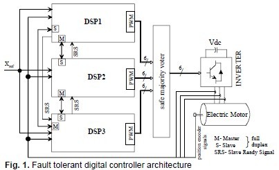
The focus of this paper is on fault tolerance of the information processing along with the tolerance to feedback sensors failure. Therefore, fault tolerance of the converter or the machine is not studied here, but there are several proposals given in literature. Fig. 1 shows the block diagram with three DSPs showing fault tolerant controller architecture applied to a drive control. The main parts of the block diagram are three TMS320F2812 DSPs from Texas Instruments. One transistor based fault tolerant majority voter board, a 3-phase 2-level IGBT IPM based inverter, current feedback, position feedback from the position encoder and an PMSM to test the validity of proposed fault tolerant digital controller. Each DSP contains two synchronous serial communication ports: one is Serial Peripheral Interface (SPI) and the other one is Multi channel Buffered Serial Port (McBSP). The McBSP can be configured as SPI master or slave. The communication between any two DSPs is in full duplex mode such that it can transfer and receive data at the same time. As the communication is in full duplex and master will only supply the clock, a slave ready signal (SRS) is used in order to make sure that the slave device is ready to transfer the data when the master initiates the data transfer (handshake). The physical communication connections between all the DSPs are developed such that there is no common point of failure.
2.1 Synchronization
As three processor-clocks of the DSPs are generated by three independent crystals, it is quite possible that they will drift out of synchronism even though they are started at the same instant of time. In order to keep three DSPs in time synchronism, timer values of three DSPs are exchanged between all the DSPs and they are modified such that they will be in synchronism. The nchronization is done in each control cycle (100µs).
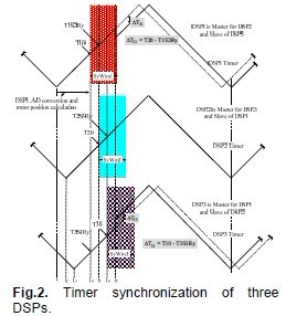
Fig. 2 shows the three PWM timers of the three DSPs before synchronization and after synchronization. At the time t1, t2 and t3, one can observe that three DSPs are asynchronous. At the time t4, DSP1 finishes its basic control routine, stores its timer counter value (T10) and issues a slave ready signal to DSP3, which captures the value T3S1Ry without any delay due to its hardware. A similar routine can be observed at t5 and t6 with DSP2 and DSP3. By the time t7, all the DSPs have exchanged their timer values and all the DSP’s have timer values from their neighbors. So it is possible to calculate the time difference between any DSP (∆T21 and ∆T13). After calculating the timer difference the slowest DSP timer counter value is updated to next faster and the fastest DSP timer counter values are updated to next slower one. This means the timer counter values of fastest and slowest DSPs are updated to medium slower / medium faster DSP timer counter. If the timer difference is high, then the update is done in steps instead of in one step. When ever a DSP issues slave ready signal to its master, it expects data transfer from its master DSP within he time frame called as synchronous window (SyWinx, x=1,2 or 3). If the master does not receive the SRS signal from slave or if the master doesn’t respond to the SRS signal within the synchronous windows time, then necessary fault detection and fault compensation algorithms are implemented based on the available information [3].

Fig. 3 shows a simple fault tolerant majority voter for a binary signal, e.g. a gate signal for an IGBT with transistors. The voter circuit has three PWM inputs A, B and C from the three processors and D is the PWM output to the inverter. The operation of the voter circuit is as follows: When at least two input terminals are at logic high,then five volts will appear across the resistive network and output D is at logic high. When at least two input terminals are at logic low, then no current flows through the transistors and R1||R2. Thus the output is at ground potential. Even a single short circuit or single open circuit failure in one of the transistors will not affect the operation of the voter [6].
3 Position sensor fault tolerance
There are several possibilities to detect encoder faults. Some are based on an abrupt change in the measured speed, which would physically not be possible. Such a step change can be caused by an encoder internal problems (e.g. loss of light in an optical encoder) or by interrupting the sensor’s cable. Here we use a back EMF based sensorless position estimation method to detect the failure of the position sensor. The estimated position or speed is constantly compared with the one measured using the encoder. Any deviation in the difference between the estimated and measured position or speed beyond specified tolerance is considered as failure in the position encoder under the condition that there is no failure in the current measurement. In order to estimate the position of the PMSM a disturbance observer is used. The disturbance observed is based on the electrical model of the machine and it estimates the back EMF [7].
The voltage equation of the PMSM in stationary reference frame can be written as,
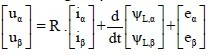
Where uα, uβ, iα, iβ,ΨL,α,ΨL,β are the components of the stator voltage, current and current dependent flux linkage vectors’, respectively. R is the phase resistance of the stator windings. eα, and eβ are the EMF vectors which can be defined as –KE. ωe . sinθe and KE .ωe . cosθe., where KE is the EMFconstant, ωeis electrical angular speed of the rotor and θerotor position at electrical angles.The EMF can be estimated using the disturbance observer. In the equation (1) has a term of the EMF eα, β, which is regarded as a kind of disturbance voltage, and the voltage eα, β is estimated using the disturbance observer. Usually the voltage eα, β varies sinusoidally but in order to develop a disturbance observer it is assumed thatde0= ![]() . The estimation error cased by this assumption is very small which can be neglected. The difference between the measured and estimated currents is used as the correction terms. Based on the above assumptions and equation (1), the observer’s equations can be written as,
. The estimation error cased by this assumption is very small which can be neglected. The difference between the measured and estimated currents is used as the correction terms. Based on the above assumptions and equation (1), the observer’s equations can be written as,
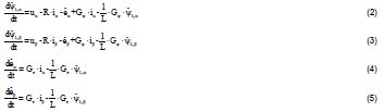
Where L is the phase inductance of the stator windings, Gψ and Geare the gains of the EMF
observer.
By solving the above equations in the digital controller, one can estimate the back EMF of the PMSM in stationary co-ordinates.
Using the estimated value of the EMF, the position can be estimated as follow,
![]()
By differentiating the estimated electrical rotor positione one can obtain the electrical speed of the rotor. In order to remove the noise of the PWM inverter in the estimated speed, a low pass filter is used. The limitation of above method is fault detection is not effective at very low speed or zero speed operation. If the application demands very low speed or zero speed operation, then different method of position estimation should be considered such as carrier signal injection or if suitable rotor saliency based method which also works at low speeds.
4 Current sensor fault tolerance
For Field Oriented Control (FOC) of the PMSM with balanced three phase windings and isolated neutral, it is enough to have current measurement from any of the two phases. In order to provide the fault tolerance to current measurement third current sensor is used measuring the third phase current.
When three phase currents are measured, there are different ways in which αβ-components of the currents can be computed [8]. The limitation of above method is if the current sensor is under fault before the machine is started, then it is difficult to detect the fault in the current sensor.
Let us say ia, ib and ic are the three phase currents of the machine, then the different ways in which αβ-components of the currents can be computed as below,
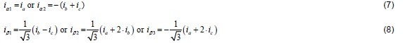
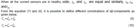

In normal operating condition, the results of the three combinations are equal and at steady state,result of the three combinations is equal to their reference values,

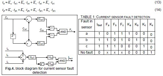
For a balanced three phase PMSM with isolated neutral and if there would be no offset in the current measurement, the sum of the three currents is zero in healthy case of all the current sensors. This principle is no longer valid when there is a fault in one of the current sensors. By using this principle and constantly comparing the Cref and Cx, (x = a, b, or c) to an error tolerance value Ctol, it is possible to find the fault in current sensor as shown in fig. 4 below and Table. 1. In order to implement the automatic controller reconfiguration in case of a fault in any current sensorsfollowing equation are implemented along with information from the Table 1.
5 Experimental result
A laboratory prototype has been built for testing the different fault tolerant solutions proposed. FOC of PMSM is implemented in order to validate the proposed fault tolerant digital controller and feedback system. Table 2 shows the different parameters of the PMSM drive. Three fixed points DSPs (TMS320F2812) are used as fault tolerant digital controllers. The experimental setup is tested for different fault conditions like a complete failure of one of the processors or a failure in communication between any two processors, a failure in slave ready signal,failure in the position sensor or failure in the current sensor. In all the cases PMSM is running as it was in healthy condition.
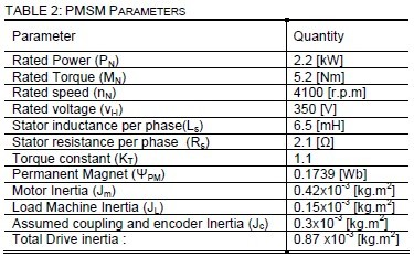
Fig. 5 and fig. 6 shows thePMSM response to different faults. Fig. 5 is the machine currents and Fig. 6 shows q-axis current, measured speed and estimated speed of the machine.First DSP3 is completely turned off and the machine is running with DSP1 and DSP2. Now at the time t= 0. 05s, current sensor fault on phase ‘a’ is inserted and machine continues to run with current sensors of phase ‘b’ and phase ‘c’. At the time t=0. 25s position sensor fault is inserted and now the machine continues to run with sensorless control.

6 Conclusions
A fault tolerant digital controller is developed using three digital signal processors (DSP) based on the triple modular redundancy (TMR). The system is tested for different faults like, a fault in any one DSP, fault in position sensor and fault in current sensors. Though the system is developed for a single arbitrary fault it can tolerate more than one fault based on the concept of redundancy with constraint that another fault should not occur on the same type of components. For example, the system can simultaneously sustain a fault in the digital controller, a fault in position sensor and a fault in the current sensors but system cannot sustain two simultaneous faults in the digital controller. The system is able to tolerate all the fault cases and the performance is as normal as when there is no fault. The validity of the above fault tolerant digital controller was tested using the FOC of PMSM.
7 Acknowledgement
This work is funded by the Deutsche Forschungsgemeinschaft DFG, Grant MU 1109/17-1,“Fehlertolerante Antriebsumrichter und deren Regelung”
8 Literature
[1] H. Schwab, A. Klönne, S. Reck, and I. Ramesohl, “Reliability evaluation of a permanent magnet synchronous motor drive for an automotive application,” European Power Electronic Conference, EPE 2003 - Toulouse ISBN: 90-75815-07-7.
[2] J. W. Bennett, A. G. Jack, B.C. Mecrow, and D. J. Atkinson: “Fault-tolerant Control Architecture for an Electrical Actuator,” 35th Annual IEEE Power Electronics Specialists Conference, Aachen,Germany, 2004.
[3] R. R. Errabelli and P. Mutschler, “A fault tolerant digital controller for power electronic applications,” European Power Electronic Conference. EPE 2009, pp. 1-9.
[4] R. B. Sepe, B. Jr. Fahimi, C. Morrison, and J. M. Miller; “Fault tolerant operation of induction motor drives with automatic controller reconfiguration,” IEEE International Electric Machines and Drives Conference, IEMDC 2001, pp: 156 – 162.
[5] S. Karimi, A. Gaillard, P. Poure, and S. Saadate, “FPGA-Based Real-Time Power Converter Failure Diagnosis for Wind Energy Conversion Systems,” IEEE Trans. Ind. Electron., vol. 55,Issue: 12, 2008, pp. 4299 – 4308.
[6] J. H. Wensley, “Fault Tolerant Techniques for Power Plant Computers, ” IEEE Transactions on Power Apparatus and Systems, Volume PAS-101, Issue 1, Jan. 1982, PP. 100- 106.
[7] R. Leidhold and P. Mutschler, “Speed Sensorless Control of a Long-Stator Linear Synchronous Motor Arranged in Multiple Segments,” IEEE Trans. Ind. Electron., vol. 54, Issue: 6, 2007, pp.3246 - 3254.
[8] I. Bahri, I. Slama-Belkhodja, and E. Monmasson, “FPGA-based real-time simulation of fault tolerant current controllers for power electronics,” IEEE International Symposium on Industrial Electronics, 2009, ISIE 2009, pp: 378 – 383.