
Triac dimmer design for low-consumption lamps
Benoit RENARD, STMicroelectronics- IMS, Rue Pierre et Marie, Tours, France
Laurent GONTHIER, STMicroelectronics- IMS, Rue Pierre et Marie, Tours, France
Abstract
In this paper we explain how dimmers using Triacs should be designed to operate properly with new low consumption lamps like CFLs and LEDs. These design guidelines are defined after an analysis of the impact of the EMI filter on the current ripple amplitude at Triac turn-on. Then, some experiments are performed to check how the control signal has to be set according to the lamp technology and model to be dimmed. Finally, the dimmer power supply concern is discussed.
1 Introduction
Due to the eco-design directive (2005/32/EC), the sale of incandescent or halogen lamps has been banned from the European market for powers greater than 100 W since 1st September 2009. This ban will be extended to 75 W, 60 W, 40 W and down to 25 W lamps by September 2012. But only class D or E lamps are currently banished. High efficiency halogen lamps will remain on the market after 2016 if they reach class B requirements at least.
Incandescent lamps are then progressively being replaced by halogen lamps but also by much more efficient lamps such as compact-fluorescent lamps (CFLs) or highbrightness light emitting diode (LEDs) lamps. These lamps can cause problems when they are dimmed by Triac dimmers, and this is especially because of the low current they sink from the Line.
2 Flickering phenomenon reminder
2.1 Holding current concern
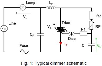
To keep a Triac on after having removed its control current, i.e. its gate current, the Triac current (refer to IT on Fig. 1) has to remain higher than the holding level, called “IH”. Generally Triacs are controlled by a pulsed gate current; this is especially the case for dimmers where the Triac is controlled by a Diac circuit as shown in Figure 1.As there is no gate current applied during Triac conduction, then its main current has to remain above the IH to keep the Triac ON. This means the load current has to be higher than IH, which is in the range of 10 to 15 mA for sensitive Triacs, for correct dimmer operation.
As the lamp current is very low, there is a high risk that the Triac current at turn-on will reach zero due to the oscillations coming from the EMI input filter (refer to LF and CF on Fig.1). This will cause Triac turn-off, so the turn-on angle will be disturbed and the light brightness could present a low-frequency fluctuation or flickering.
2.2 EMI filter impact on flickering
As explained in next section, light dimmers require an EMI filter at their input (refer to CF and LF on Fig.1). These two reactive elements achieve a resonant circuit that will oscillate each time the Triac turns on.
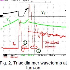
Figure 2 shows a zoom of the Triac current at turn-on. When the voltage across the diac (VC) reaches its VBO, then the Triac is triggered. This results in CF discharge through LF and the Triac. The current then shows a demi-sinusoidal form and reaches zero at point 1. Then the Triac turns off, the voltage is reapplied back across the Triac, and C is charged again. VC reaches VBO again, and the Triac is triggered again. Here, the „switched current“ is higher as the Line has slightly increased since the last turn-on. IT stays above IH level on point 2 and the Triac remains ON. But this phenomenon leads to a bad dimming angle control (as shown in Fig. 3) and to lamp flickering.
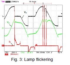
The flickering issue will mainly ocur when the switched current is low, as the filter oscillations have a higher chance to get the Triac current to zero. Low consumption lamps, which feature lower RMS currents, are therefore more likely to cause this concern.
2.3 EMI filter optimization to reduce current oscillations
EMI filter design greatly depends on the targeted market. For the European market,since the 1989 EMC directive (89/336/CEE), now replaced by 2004 directive, 2004/108/CEE, a filter is mandatory to filter the noise coming from the Triac switching and then to keep the conducted noise below the limits defined in the EN55015 standard.
For European dimmers (220-240 V Line), the LF inductor is usually between 0.7 to 2.2 mH, with a CF capacitor from 47 to 470 nF, and this is for a power range from 100 to 500 W.
For the US market, there is no particular mandatory EMC standard to fulfill. The main concern of US dimmer OEMs is to propose dimmers which do not disturb radio equipment and do not produce too much acoustic noise (for example, if the load current transient is too fast, it produces mechanical vibrations of the lamp filament that cause noise).
For US dimmers (100-120 V Line), the LF inductor is between 10 to 100 μH, with a CF capacitor from 47 to 220 nF, and this is for a power range from 300 to 1000 W.
As demonstrated previously, these two filtering components have a great impact on the flickering issue occurrence. To analyze it, we use the following equation that gives the CF current during the oscillations of this LF-CF resonant circuit after a Triac turn-on:
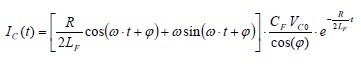
With VC0 = CF initial voltage;
R = serial equivalent resistor of both CF and LF
ω and ϕ = respectively, the pseudo-frequency and the phase of the R-LF-CF circuit
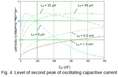
Figure 4 gives the absolute level of the second peak of the oscillating wave of IC current (i.e. the first negative one which can lead to Triac turn-off).
It can then be said that for European Line applications, increasing the filter inductor value above 0.5 mH always helps to reduce the second IC peak current. For example, a 1.3 mH value versus a 0.5 mH one will decrease the second peak current by 30%, for a 100 nF capacitor. Reducing the capacitor value also helps to reduce the peak current. The variation is almost linear from 50 to 500 nF.
For the US market, it’s better to keep the inductor lower than 5 μH and then increase the capacitor to values above 200 nF.
3 Triac dimmer design
3.1 Gate pulse width and dimming range definitions
The current sunk by CFL lamps is typically in the range of 50 to 200 mA as most CFLs feature a 10 to 25 W consumption. But this current, due to the internal diode bridge and filtering DC capacitor, could not be sunk during the whole Line cycle. For LEDs, as brightness efficiency could reach 100 lm/W, which is even higher than CFL (60-80 lm/W) and much higher than halogen lamps (15-25 lm/W). Furthermore, mainly due to power dissipation concerns of the AC/DC converter that controls the LED current, LED lamps are limited to the range of 1-5 W. The Line current is then in the range of 5-30 mA.
With a 100 nF 1.3 mH filter, optimized thanks to the analysis outlined in the previous section, we have performed several tests with CFL and LED lamps. Such a filter is enough to fulfil the EN55015 standard for a 500 W 230 V halogen lamp. The 50 Hz RMS line voltage was set from 198 to 264 V to cover the entire operating range.These experimental results allow us to define how long the gate current pulse has to be in order to ensure right Triac dimmer operation with such lamps, i.e. what is the required pulse width (refer to tP on Table 1) to reach a lamp current higher than the maximum IH (max. specified value +20% for operation at 0°C, i.e., 18 mA for a BTB04-600SAP Triac).
The tests have also been performed to find out the maximum turn-on delay (tON) range for each lamp that will not lead to flickering. Table 1 presents these tests’ results.

3.2 Dimmer supply concerns
According to the results shown in Table 1, the required pulse width to properly dim each kind of lamp is 2.4 ms. Such a pulse width cannot be reached with the schematic of Fig.1 where the only way to enlarge the pulse width is to increase the R1 resistor. Then the concern is that the gate current is also reduced. Practically speaking, the highest pulse widths that can be set with such a schematic are around 20-50 μs.
To reach a 2.4 ms pulse, a microcontroller (MCU) has to be used. Then the major concern is to supply enough current for the whole control circuit including the MCU,the Triac gate, and also all consuming devices, like for example, signal LEDs.
For the gate current, if a 10 mA IGT device is used (like a BTB04-600SAP), then a 13mA has to be applied to ensure device triggering correctly at the lowest operatingtemperature (usually 0°C). The required average current is then around 3.12 mA.
Then, taking into account a 0.3 mA for the MCU (or an ASIC), the supply has to deliver at least a 3.42 mA current. For such consumption, a capacitive load is out of the question, especially as the capacitor would be totally discharged at each Triac turn-on in a two-wire topology (as the supply is implemented in parallel to the two dimmer terminals), and therefore the dimmer power losses would drastically increase.
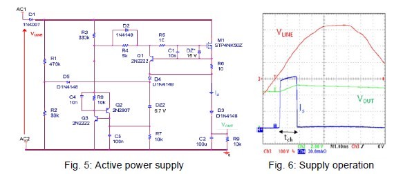
The common and low-cost solution is to use an active power supply as shown in Fig. 5. In this schematic, MOS M1 is normally-on as its gate is charged through R3-D2-R5. It achieves a constant current source which peak current is set by the Q1 baseemitter voltage divided by R6 resistor (around 60 mA for 10 Ohm). As the MOS is working as a current source, it has to be turned off to limit its power dissipation. MOS turn-off occurs then either if the output voltage or the MOS voltage seen through R1- R2 divider reaches Z1 Zener diode threshold. This will activate the SCR, achieved by Q2 and Q3, and discharge M1 gate.
Figure 6 shows the waveforms of such a power supply directly connected to a 230 V Line.
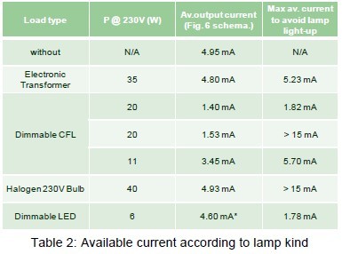
Using such an active supply in series with a CFL or LED lamp leads to two concerns:first, the lamp impedance is high and therefore will limit the available supply current; secondly, if the current sunk by the MOS is too high, it could light up the lamp. Table 2 gives the experimental results of the maximum average current when the schematic shown in Fig. 5 is put in series with several lamps to demonstrate the impact of the lamp impedance on the supply current capability. Table 2 also gives the maximum average current that can be sunk by the supply (by decreasing R6 value) for which the lamp begins to light up or to flicker.
This table shows that all lamps (except the two 20 W CFLs) can be connected in series with Fig. 5 supply and a high enough current will be delivered to the MCU. But it should be noted that for the LED lamp, as soon as the Q2-Q3 Thyristor is latched, the lamp is lighted. To avoid this lamp light-up, a current less than 1.78 mA has to be sunk at ZVS.
But unfortunately for one of the 20 W CFLs and for the 11 W one, there is a small light flickering certainly due to the fact that the ballast IC is disturbed by the supply current and cannot correctly detect the Triac turn-on angle.
4 Conclusion
Guidelines have been given to allow the enhanced operation of Triac-based dimmers operating with CFL and LED lamps. This analysis shows that Triac dimmers and lowconsumption lamps can work together as long as the filter, the MCU software, and the supply are all well defined. Lamps ballasts also have to respect some requirements to achieve good dimming behaviour, and in particular, they should provide enough current at low voltage for the dimmer supply and distinguish this supply current from the Triac turn-on angle.
5 References
[1] Low-Cost Dimmer for Dimmable Low-Consumption Lamps, L.Gonthier, A. Passal,PCIM China, June 2010.