
New Generation of IPM for Home Appliance Application: Focusing on Efficiency and Reliability
Zhou Chen, International Rectifier, USA, jchen3@irf.com
Abstract
The new generation of Integrated Power Module (IPM) is introduced in this paper for home appliance applications. The combined benefits of advanced Trench IGBT technology and optimized package design have enabled us to achieve higher efficiency and improved reliability, along with minimized module and system cost. The Trench IGBT is able to deliver up to 30% loss reduction compared with NPT IGBT of same die size. Besides, the new IPM has achieved as much as 50% reduction in IGBT junction temperature ripple, thanks to the thermal mass provided by heat spreader.
1. Introduction
Integrated Power Modules are becoming more popular in the home appliance applications, because of smaller size, easier assembly and shorter development time. Our next generation IPM is developed with the focus on improving the module efficiency and long term reliability.
With the global emphasis on energy efficiency,appliance market has ever stricter requirement on the efficiency of motor drive circuit. The smaller power losses also mean that we will be able to reduce the size of heatsink, hence lowering the total system cost.
In term of module reliability, studies have shown that the life time of IPM is directly related to the junction temperature variation. It will be demonstrated that the Tj ripple can be dramatically reduced,at the worst case of low speed operation,with the addition of heat spreader
2. Trench IGBT
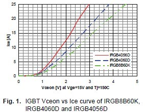
The Trench IGBTs offer significant improvement in terms of loss reduction, over the last generation of Non-Punch-Through (NPT) IGBTs. For example, Fig. 1 shows the comparison of Vceon vs Ice of NPT IRGB8B60K, Trench IRGB4056D and IRGB4060D [1]. While the first two IGBT have the same die size, the last one is about 20% smaller. It is quite clear that the conduction losses can be reduced as much as 30%, for the same die size. Even with the smaller die, it is still possible to achieve 10% loss reduction. Since the switching characteristics are quite similar between Trench and NPT IGBTs, the switching loss will largely remain unchanged.with the addition of heat spreader.
As we know, the current rating of IPM are fundamentally determined by the IGBT power losses and IGBT junction to case thermal resistance, as showing in the equation below.ΔTjc = Ploss * Rthjc
Where IGBT Ploss is a function of motor current.Rthjc is mainly decided by the IGBT die size, assuming we are using the same module package.The ΔTjc is usually set at 50ºC which is derived from Tjmax=150ºC and Tcmax=100ºC.
The IGBT technology advancement brings two potential opportunities for the new IPM development.On one side, we can keep using the same size of IGBT die. In this case, the Rthjc will remain same, while Ploss at the same current will become smaller. Therefore, we can increase the current rating while still maintaining the ΔTjc ≤ 50ºC. For example, it is quite feasible to develop modules with current rating of 15A, instead of 10A, with same module package. Therefore, the appliance manufacturer will be able to expand the power range of their motion control board,without pursuing of bigger sized modules.
On the other side, we can use smaller IGBT die if we want to create modules with same current rating. For example, as shown in Fig. 1, it is now possible to replace IGB8B60K with IRGB4060D which is 20% smaller and achieve lower module cost. The Rthjc will be bigger in the case. However,it will be compensated by smaller power losses of Trench IGBT. In the end, we can still meet the requirement of ΔTjc <= 50ºC. As an additional benefit, the new IPM can use smaller heat sink which also brings down the system cost.
3. Package Design
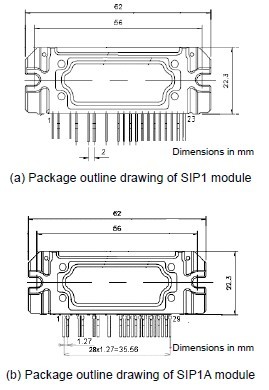
In order to offer more functions and features, a new package has been developed. Fig. 2 shows the package drawings and photos of the new 29 pin SIP1A package vs. the previous 23-pin SIP1 package. The molded portion of SIP1A is identical to SIP1; however it offers 29 pins with smaller pitch distance (1.27mm vs. 2mm). Between the high voltage pins, extra space is provided in order to satisfy the clearance and creepage distance requirements mandated by UL/IEC standards.
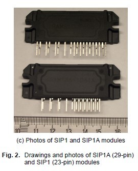
The SIP1A package offers separate pins for Itrip (over current protection), TH (temperature sensing) and FLT/EN for fault output and enabling/ disabling function, in the open emitter version as shown in Fig. 3(a).
Unlike the modules with separate DBC and PCB construction, the temperature sensing is quite accurate and provides fast tracking of Tj because the thermistor is located very close to the IGBT on the same substrate. This will enable sophisticated temperature protection and control of the IPM.
In case of common emitter version with single bus shunt, more pins can be used to provide additional functions, such as RCIN (programmable fault reset time), ISD (programmable over current protection threshold) as shown in Fig. 3( b).These individual pins give the IPM customer great flexibility in their design.
The new package also provide the possibility of additional functions like DC bus overvoltage protection,ground fault protection, as well as further system integration like diode bridge and PFC front end.
4. Thermal Design
The smaller and thinner IGBT die provides a new challenge in the thermal design. Because of its small thermal mass, the IGBT junction temperature tends to swing a lot, especially at the lower modulation frequency, for example 3Hz. In order to improve the transient thermal performance and reduced the junction temperature ripple, we have added copper heat spreaders (HS) of 1mm thick underneath the all six IGBTs.
Fig. 4 shows the thermal impedance (Zthjc) curve of IGBT. The red solid curve is the Zthjc curve of module without heat spreader, and the blue dashed curve is for the module with HS.There is a slight difference in the Rthjc value (when time is infinite). The reason is that while the added heat spreader constitutes one additional layer in the heat transfer path, it also helps to spread the heat across its bottom surface due to copper’s excellent thermal conductivity. Therefore, the layers beneath the heat spreader will have larger effective area for the heat transfer.
The big difference lies in the time range from 0.01s to 1s. It can be seen clearly that heat spreader has helped to achieve much lower thermal impedance. Especially at 0.1s time range, which corresponds to module operation condition of fmod=3Hz, the thermal impedance is reduced by almost 50%. The measurement of IGBT junction temperature shown in next section also verified this advantage.

While the benefit of heat spread is significant in lower speed operation, it is less critical when the motor is running at high speed. For example at fmod=50Hz, the IGBT temperature is mainly determined by the Rthjc value, plus the smaller Tj ripple determined by Zthjc at 5ms range. It is quite clear from Fig. 4 that the difference of thermal impedances is quite small at this time range.
5. Power Cycling Test
Based on the above package and thermal design, we have released a new family of IPMs,such as IRAM136-1061A [2], utilizing TrenchIGBT and SIP1A package.
These new modules have been qualified to industrial level, with HTRB, THB, TC, Autoclave and IOL tests according to various standards like JESD/MIL. The samples size used in each qualification test is 24 modules total from three different lots.
In addition, we have completed a power cycling test where the IRAM136-1061A modules have been subjected to 5000 hours of on and off cycles.Each cycle consists of 2s on and 8s off period with a total of 1.8 million cycles.
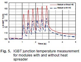
In the 2s on period, the modules are running at 300Vdc bus voltage, 16kHz switching frequency and 3Hz modulation frequency, conditions that are quite common for IPM used in washing machine in tumbling mode. The PWM scheme is over modulated to achieve 5Arms at low speed.Each IGBT went through 6 power cycles in the 2s on period. A high speed Infra-red camera has been used to capture the junction temperature variation within this period. Fig. 5 shows the measured Tj vs time, for the module with and without heat spreader. It is quite obvious that the additional thermal mass provided by heat spreader greatly improved the transient thermal performance.
The difference in IGBT temperature ripple can also be validated using the power loss calculation and the thermal impedance curves shown in Fig. 4.
At this specific operation condition, the software tools developed in [3] was used to simulate the power losses of IGBT. The red solid curve in Fig. 6 shows the calculated power loss waveform over time.
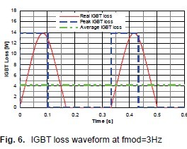
In order to calculate the junction temperature, the simplified waveform of blue line is used, which has the same peak loss (13.9W) and same average loss (4.2W). The duty time of the blue curve and be calculated as:
DT = Ppk / Pavg * Tmod
Where Tmod is 0.333s. Hence DT is about 0.1s.The first pulse of IGBT junction temperature rise can be derived using the following equation:
ΔTjc = Ppk * Zthjc (DT)
The measured value of ΔTjc shown in Fig. 5 is about 20ºC and 40ºC for the module with and without the heat spreader. While the Tj calculation does show the big advantage of the added heat spreader, there are discrepancies between the calculated and measured Tj. The main reasons are:
1. Accuracy of loss model which is based on conduction and switching loss measured at Tj=150ºC. In the power cycling test, the Tj is lower therefore the loss should be smaller too.
2. The method used in calculating the ΔTjc can be improved by using the real loss waveform,instead of the simplified curve of fixed Ppk lasting for fixed duty time. It will result in smaller calculated ΔTjc.
Since the module life time is directly related to junction temperature ripple, it is expected this new module will have improved long term reliability.
6. Conclusion
A new generation of more efficient and reliable IPM is presented in this paper. It has been shown that Trench IGBT technology is able to deliver 30% loss reduction. It has also been demonstrated that the new IPM has reduced the IGBT temperature ripple by as much as 50%, thanks to the added heat spreader. In addition,with the new SIP1A package design, it is expected that additional HVIC functions and more components can be integrated in to the IPM in the future.
7. Literature
[1] Datasheets of IRGB8K60, IRGB4056D and IRGB4060D, International Rectifier,http://www.irf.com
[2] Datasheet of IRAM136-1061A, International Rectifier, http://www.irf.com
[3] Chen, Z.;, Bolloju, V.; Wu, W,: How to Choose the Right Integrated Power Module for Ap-pliance Application, PCIM China 2007