Shucheng, Wang, Fairchild Semiconductor, China,
The Power Point Presentation will be available after the conference.
Abstract
The permanent magnet synchronous motor (PMSM) control is based on the back-EMF estimation. But this method is sensitive to many parameters. In this paper, a parameter estimation method has been introduced. The resistance, the inductance, and the back-EMF constant can be estimated on-line. The simulation results illustrate the validity of the proposed method.
1. Introduction
The PMSM has many advantages. Compared to the DC motors, they require lower maintenance due to the elimination of the mechanical commutator and they have a high-power density, which makes them ideal for high-torque-to weight ratio applications. Compared to induction machines, they have lower inertia allowing faster dynamic response to reference commands. They are also more efficient due to the permanent magnets which result in virtually zero rotor losses [1].
Because of the development of digital control technology, it’s possible for PMSM position sensorless control. The PMSM position sensorless control can be widely used in air conditioner, refrigerator, water pump, and fan. Generally, this control method is based on the observer of back- EMF[2-3], however, the sensorless control is sensitive to the motor parameters. At the worst condition, the PMSM maybe step out if the parameters are not accurate.
An online identification method for stator resis-tance and back-EMF constant had been present in [3]. In [4], the resistances, the voltage error due to the inverter, and the d-axis and q-axis in-ductances are identified at standstill, and the flux linkage of the permanent magnet is identified at the operating state.
2. PMSM Position Sensorless control and Parameters estimation
2.1. Position Senserless Control for PMSM
The d-q axes voltage equation on a synchronous rotating reference frame (SRF) can be expressed as following:

Where the superscript r means the corresponding variable is defined on a SFR, rs denotes the stator resistance, Ld and Lq denote the d and q-axis stator inductance, respective, Ke denotes the back-EMF constant, and ωr denotes the angular velocity.
If the error between the actual and estimated rotor angle is assumed to be sufficiently small so that the difference between the stator inductances on the actual SRF and the estimated SRF due to rotor saliency can be neglected, the d-q axis voltage equation on the estimated SRF can be derived from (1) as the following.

where ,  ,θ and
  denote the actual and estimated rotor angle, respectively. The de-tailed relationship between these two frames has been shown in fig.1.
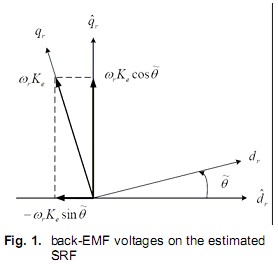
By defining the back-EMF voltage as the state variables like

(2) can be rewritten as the following state-space matrix equation.
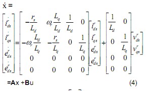
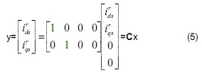
From (4) and (5), the back-EMF voltage observer can be designed as the following [3].
![]()
where the matrix L denotes the observer gain matrix.
In the back-EMF voltage observer, the angle er-ror can be estimated by divide the estimated d-axis back-EMF voltage by the estimated q-axis back-EMF voltage as follows:

From (7), the rotor angle can be updated in digital domain as the following.
![]()
Once the rotor angle can be estimated, the system can be operated as the position sensor control.
2.2. Parameters Estimation for PMSM Sensorless Control
If position observer’s error is assumed to be suf-ficiently small, the estimated rotor angle and the rotor frequency are believable. That means we assume the equations are the following:
![]()
Based on the assumption (9), the d-q axes voltage equation (1) on SRF can be derived as the following.

In the voltage equation (1), there are 4 parameters ( rs , Ld , Lq , and Ke ) in the matrix. To calculate the parameters, the parameters should be taken as the unknown item, and the voltage equations (10) can be written as the following.

In (11), it means that the 2 equations can be obtained one time in a sampling cycle during the motor operation. We can accumulate the cycle’s data to get sufficient equations to calculate the parameters. If there are 2n equations are used for parameters estimation, they can be merged as the following.
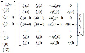
In (12), there are only 4 parameters for estimation, but there are 2n equations. To get the optimal answer for the equations, the least square method is used. (12) can be simplified and written as the following.
V = MP
Where 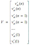 ,
, and M is the coefficient matrix in (12) From the least square method, the optimal answer is


In fig.2, the motor control flow chart has been shown. After the rotor angle and the rotor frequency are observed, the matrix A is updated. After some cycle, the parameters will be calculated one time. The updated parameters will be reused to calculate the observer gain matrix L
3. Simulation Result
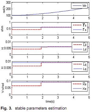
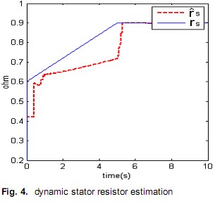
To verify the validity of proposed calculation method, the control and the estimation system has been simulated. Fig.3 shows the estimated parameters culver. Each parameter’s original estimated value is 70% if the actual value before the calculation starts. The estimated parameters reach to the actual value rapidly at the beginning of calculation. Each estimated parameter error is very small and stable even when rotor speed is increasing. Fig.4 shows the sr ˆ estimation result when actual sr increased fast from 0.6ohm to 0.9 ohm in 5 second. The original sr ˆ is also 70% of sr. At the increase stage, the calculation response is slow. Considering sr increased 50% in only 5 second (it is unreasonable fast) and there is no big vibration during the estimation, the result is acceptable. And once stator resistor is stable, sr ˆ increases to the actual value very fast.
4. Conclusion
The proposed estimation method can arrive at the optimal result theoretically. In the simulation, each estimated value can reach to the actual value fast if each parameter is stable. The dynamic result is acceptable in engineering.
5. Literature
[1] Fernando Rodriguez and Ali Emadi, “A Novel Digital Control Technique for Brushless DC Motor Drives,” IEEE Trans. Ind. Electron., vol. 54, no. 3, pp. 2365-2373, Oct. 2007.
[2] Yo-Chan Son, Bon-Ho Bae and Seung-Ki Sul , “Sensorless Operation of Permanent Magnet Motor Using Direct Voltage sensing Circuit,” IEEE Industry Applications Conference, vol. 3, , pp. 1674-1678, 2002.
[3] H.M.Ryu,” Synchronous Reference Frame d-q Modeling of Interior Permanent Magnet Synchronous Motor (IPMSM) ,” unpublished.
[4] Kyu-Wang Lee,Doo-Hee Jung and In-Joong Ha, “An Online Identification Method for Both Stator Resistance and Back-EMF Coefficient of PMSMs Without Rotational Transducers” IEEE Trans. Ind.Electron., vol. 51, no. 2, pp. 507–510, Apr. 2004.
[5] Shigeo Morimoto, Masayuki Sanada and Yoji Takeda, “Mechanical Sensorless Drives of IPMSM with Online Parameter Identification,” IEEE Trans. Ind. Application, vol. 42, Nov. 2006.