
Actuator
Jiabin Wang, Kais Atallah and James Barnes
Dept. of Electronic and Electrical Engineering, The University of Sheffield, Mappin Street, Sheffield, S1 3JD, UK
Abstract
This paper describes analysis and design of a novel high force density linear electromagnetic
actuator based on the concept of magnetic screw-nut, in which helically disposed, radially
magnetized permanent magnets are placed on both the screw and the nut, as shown in Figure 1.
Magnetic force and torque can be developed between the two parts without direct mechanical
contact. Analytical and numerical analysis has been carried to predict the performance of the
magnetic screw-nut assembly. It has been shown that a thrust force density in excess of
10MN/m can be achieved for airgap lengths varying from 0.4mm to 0.8mm and a lead greater than
7mm.
When combined with a naturally cooled permanent magnet brushless machine having a torque
density of ~15kNm/m3, shown in Figure 2, the resulting thrust force density of the combined
system, i.e. electrical machine and magnetic screw-nut assembly, is an order of magnitude higher
than that of a liquid-cooled tubular permanent magnet brushless machine. The issues pertinent to
the realization of the helically disposed, radially magnetized permanent magnets will also be
discussed.
1. Introduction
Linear actuators provide thrust force and displacement for many applications, ranging from industrial automation to automotive and aerospace actuation. There are various linear actuator
technologies, whose suitability depends on the force, stroke and dynamic performance
requirements, as well as cost, reliability and maintainability considerations. Although piezoelectric
actuators offer a high force capability and a high bandwidth, they only have a very limited stroke,
of the order of a few millimetres. For the vast majority of applications, therefore, for which
significantly longer strokes are generally required, one of the following actuator technologies is
usually employed. Hydraulic actuation exhibits very high force densities over large strokes, typical
fluid pressures ranging between 7MPa to 35MPa (~1000psi to ~5000psi). However, since the
force capability is
directly proportional to the pressure the provision and containment of the hydraulic fluid adds
weight, compromises reliability and increases the maintenance requirement and cost. By way of
example, the power transmitted by a 10mm bore diameter pipe with hydraulic fluid at 35MPa
(~5000psi) travelling at 4m/s (~13ft/s) is ~11kW, which compares to more than 100kW which
can be transmitted by a 10mm diameter copper conductor at a current density of 5A/mm
and a voltage of270V. In addition, hydraulic actuation has an inherently low bandwidth,
typically below 10Hz.
Pneumatic actuation exhibits a significantly lower force density than hydraulic actuation, since
the pressure is generally between 550kPa and 700kPa (~80psi to 100psi). Similarly, however, the
containment may compromise reliability and increase the maintenance requirement.
Electromechanical actuation is usually achieved by converting rotary-to-linear motion, by using
ball/roller screws, which result in high force densities. By way of example, an off-the-shelf ball screw
with a 40mm diameter and 50mm long nut has a dynamic load rating of 25kN, which results in a
nominal fatigue life of 106revolutions and 90% reliability. However, the dynamic load rating will be
reduced if the reliability and/or fatigue life requirements are increased. Further, jamming caused by
a failure of the screw or drive gearbox has been a significant problem in safety critical applications,
such as aircraft flight control surface actuation. In general, the achievable motion control
performance and dynamic bandwidth of this actuation technology are significantly compromised due
to backlash, non-linear friction and elastic deformation of the mechanical transmission.
Electromagnetic actuation offers many advantages, in terms of being virtually maintenance free
and having a high efficiency over wide operating conditions. A tubular permanent magnet machine
topology reported in [1-5] offers the highest thrust force density of ~0.6MN/m
3 when liquid-cooled.This figure can be increased significantly if the machine is coupled to the load by a linear magnetic
gear, which exhibits a thrust force transmission density in excess of 2MN/m
. The resultantcombined system thrust force density is ~0.85MN/m323
Paper 19 [6]. However, this is roughly an order of
magnitude lower than that of electromechanical actuation in which rotary-to-linear motion is
achieved by using ball/roller screws.
This paper presents an alternative approach to realising linear electromagnetic actuation. Fig. 1
shows a schematic of a magnetic equivalent of a mechanical screw of the type which is employed in
electromechanical actuators, in which the threads on both the nut and the screw are replaced by
helically disposed, radially magnetized permanent magnets. Therefore, magnetic force and torque
can be developed between the magnetic nut and the magnetic screw without direct mechanical
contact. Similar to the mechanical counterpart, 360o rotation of the nut results in the magnetic screw
being displaced by a linear distanceλ, which is equal to twice the magnetic pole-pitch, and vice-
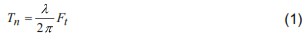
versa. Based on the principle of energy conservation, the torque Tand the thrust force F
are related, under ideal condition, by:
Thus by appropriate selection of the magnetic pole-pitch, a very high thrust force can be
achieved through the same gearing effect of the mechanical ball screw, but this approach is
contactless and jam-free. Although similar concepts [7-9] have been reported, the achieved force
density is far lower and detailed analysis is absent in literature to date.
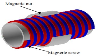
Fig. 1. Schematic of magnetic screw-nut assembly
2. Analysis of magnetic screw-nut assembly
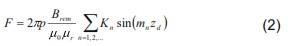
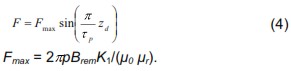
An analytical expression for predicting the transmitted thrust force by the proposed magnetic
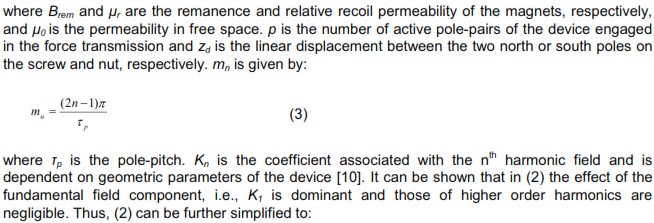
screwnut assembly has been established in [10] and is given by:
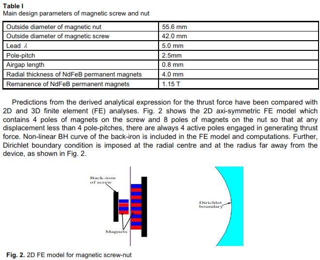
To validate the analytical prediction of thrust force, numerical analysis has been performed for a
4pole magnetic screw-nut assembly shown in Fig. 1 for which the main design parameters are
given in Table I.
Figures 3 (a) and (b) show the flux density distributions, respectively, when the magnetic poles on
both the screw and nut are aligned with each other and when the magnetic poles on the screw are
displaced by half a pole-pitch with respect to those on the nut. As will be seen, when the relative
displacement between the N or S poles on the screw and nut is zero, i.e, z
= 0, the magnetic field di stribution is symmetrical with respect to the axial centre of the device and the resulting thrust force is zero. However, when the displacement between the magnetic poles increases, the tangential
component of the airgap flux density becomes significant, and the thrust force will be developed.
This force will reach a maximum when the displacement is half a pole-pitch or 90 electrical degrees,
Figure 4 compares the analytically and 2D FE predicted thrust force as a function of the axial
displacement, z. As will be seen, the analytical prediction agrees very well with the FE result, and
the maximum difference between the two is less than 3%, which are mostly likely due to the effect of
saturation that is neglected in the analytical prediction.
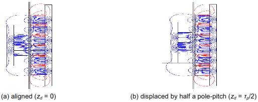
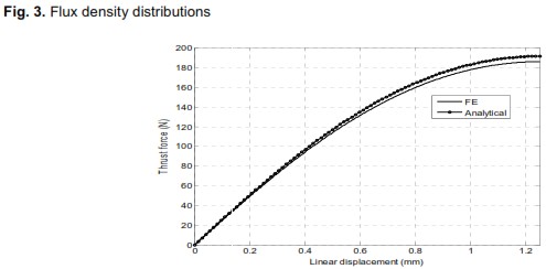
Fig. 4. Comparison of analytically and nalytically and FE predicted thrust force variation
To further validate the analytical and 2D FE models, 3D FE calculations were also performed.
the 3D model and its meshes. To reduce the model size and computation time only 4
poles of magnets are modelled on both the screw and nut. Thus, when the screw is displaced with
respect to the nut by a small distance, the active surface area will be slightly less than that of 4 pole
pitches. This will lead to a small reduction in the thrust force. To take this effect into account, the 2D
FE model is also modified to have 4 poles of magnets on both sides.

Fig. 5. 3D FE model and finite element mesh finite element meshes
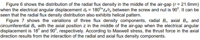
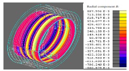
Fig. 6. Distribution of radial flux density component Br in air-gap at electrical angular
displacement = 90 degree
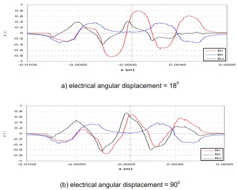
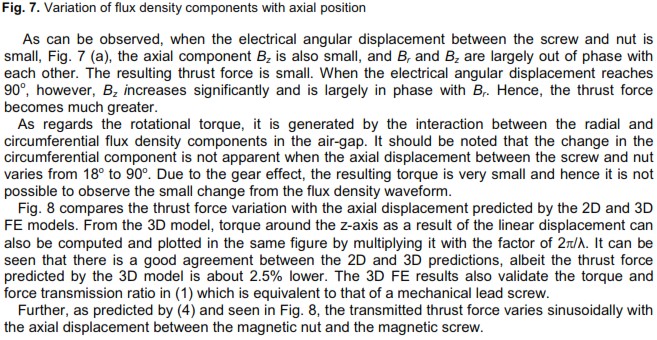
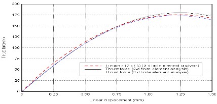
Fig. 8.Variation of thrust force with relative axial displacement between magnetic nut and magnetic screw.
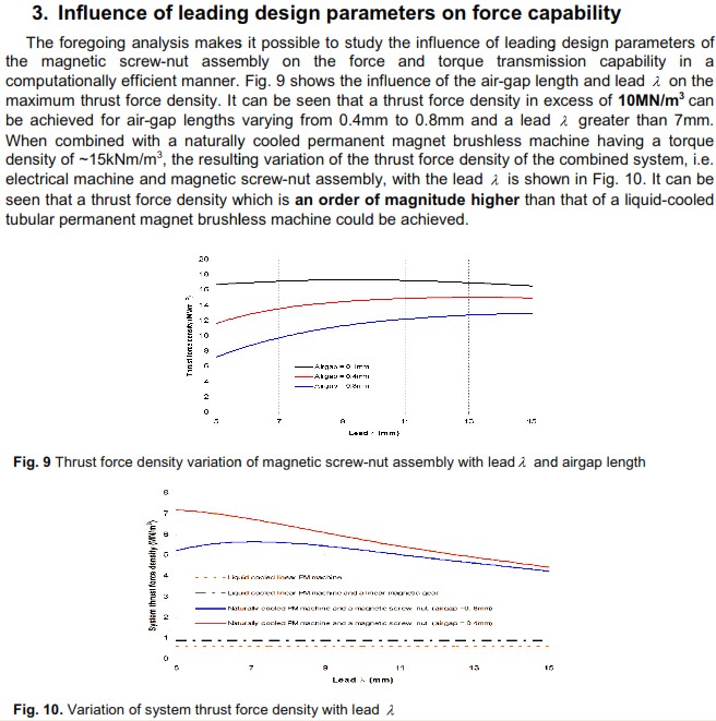
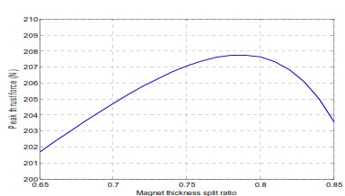
Fig. 11. Variation of peak thrust force with the magnet thickness split ratio
Figure 11 shows the variation of the peak thrust force with the split ratio of the radial magnet
thickness, which is defined as the ratio of the radial thickness of the magnets on the screw to the
total radial thickness of the magnets on both the screw and nut, when the total magnet thickness is
kept 8.0mm, the air gap is 0.8mm and the pole pitch is 2.5mm. As can be seen, there is an optimal
ratio of 0.78 which yields the maximum thrust force capability. Compared to the split ratio of 0.5 in
the previous design, i.e., the radial thickness of the magnets on both the screw and nut are the
same, the optimal split ratio yields ~ 10% greater force while the total magnet volume is virtually
kept the same. From a practical point of view, of course, there should be a limit on the minimum
thickness of the magnets on both the screw and nut.
4. Integration and dynamic coupling
By integrating the magnetic screw-nut assembly with a rotary permanent magnet brushless motor,
a high force density tubular electromagnetic actuator as illustrated in Fig. 12 can be realised. In Fig.
12 (a) the magnetic nut is an integral part of the rotor of an internal rotor permanent magnet
brushless machine, whilst in Fig. 12 (b) the magnetic nut is integrated with the rotor of an external
rotor machine. However, the relative merits of such linear electromagnetic actuator topologies are
dependent on many factors, such as dynamic response, thermal condition, mechanical integrity and
stiffness requirement as well as ease of manufacturing and assembly. Further, these proposed
topologies are given only by way of example, and alternative methods of integrating a magnetic
screw system with a permanent magnet brushless machine should become apparent when
application specific designs are evolved.
Assuming that the magnetic nut rotates and the magnetic screw translates, and neglecting
damping forces, the equations which govern their motions are given by:
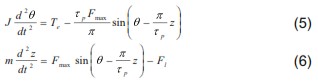
where z and θ are linear and rotary displacements, respectively, T
is the electromagnetic torque of the motor and Fle is the load force. m is the combined mass of the actuator-load system associated with the linear movement while J is the moment of inertia of the actuator associated with the rotary
movement. The electromagnetic torque applied to the nut by the permanent magnet brushless motor is
transmitted to the screw as the thrust force by the “gearing” action of the magnetic screw and nut
assembly so as to realise a desirable linear actuation.
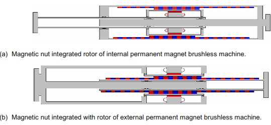
Fig. 12. Schematic of linear electromagnetic actuator employing a magnetic screw-nut assembly
5. Magnetization
Two primary strategies for achieving the helical magnetization effect are being studied: firstly,
concentrically aligned helically magnetized rings; secondly, a helical arrangement of individual
magnets glued into a steel groove in a solid backiron piece. The physical constraints regarding both
magnetization and construction mean both methods are useful for different design regimes. Where
magnetization becomes considerably difficult for small lead values, for example below 10mm, the
second approach is preferable. The magnetization study has concentrated on the analysis of the
magnetization process for NdFeB rings since they have the potential to achieve the high force
densities of interest in this design topology. Analysis of the various plausible magnetizing fixture
designs yields a preferred multi-pole configuration: a twin start double sided fixture with four series
connected wires bundled in each helical slot. Alternative geometries were also effective; however
comparisons show a high level of sensitivity to variation of the resistance and inductance through
geometrical changes.
6. Conclusion
A novel high force density linear electromagnetic actuator employing the concept of magnetic screw
and nut has been presented. An analytical expression for predicting the thrust force of the actuator
has been validated by both 2D and 3D FE analyses. The 3D analysis has shown that the torque and
force transmission relationship of the device is equivalent to a mechanical lead screw. It has been
shown that a thrust force density in excess of 10MN/m3 can be achieved. When combined with a
naturally cooled permanent magnet brushless machine having a torque density of ~15kNm/m
, the resulting thrust force density of the combined system is an order of magnitude higher than that of a
liquid-cooled tubular permanent magnet brushless machine. Dynamic equations which govern the
rotary and linear motion of the device have also established. Simulation of the magnetization
process for production of helical patterns on NdFeB rings has been undertaken and effective fixture
designs have been selected.
7. References
[1] J. Wang, G. W. Jewell and D. Howe “A general framework for the analysis and design of tubular linear
pe
rmanent magnet machines”, IEEE Trans. on Magnetics, vol. 35, No. 3, pp. 1986-2000, 1999
[2] J. Wang and D. Howe, “Design optimisation of radially magnetised, iron-cored, tubular permanent magnet
machines and drive systems”, IEEE Trans on Magnetics, vol. 40, no. 5, pp. 3262-3277, 2004.
[3] J. Wang, G. W. Jewell, and D. Howe, “Design optimisation and comparison of tubular permanent magnet
machine topologies”, IEE Proc. Pt B. Electric Power Appl., vol. 148 no. 5, pp. 456-464, 2001.
[4] J. Wang et al ‘Tubular modular PM machines equipped with quasi-Halbach magnetised magnets – Parts I
& II’, IEEE Trans. Magnatics, vol. 41, no. 9, pp. 2470-2489, 2005.
[5] N. Bianchi, S. Bolognani, D. D. Corte, and F. Tonel, “Tubular linear permanent magnet motors: an overall
comparison” IEEE Transactions on Industry Applications, vol. 39, no. 2, pp. 466 – 475, 2003.
[6] K. Atallah et al, ‘A novel high-performance linear magnetic gear’, IEEJ Trans. IA, vol. 126, no. 10, 2006.
[7] J. Hashimoto et al, ‘A magnetic screw device’, US patent No.: 5,687,614, 1997. (Lapsed in 2005)
[8] J. Hashimoto et al, ‘Principle and basic characteristics of magnetic lead screw mechanism’, Int. Conf. on
Micromechatronics for Information and Precision Equipment, pp. 244-249, Tokyo, July 1997.
[9] N. J. Vitale et al., ‘Optimization of drive screw pitch in a pulsatile ventricle assist device’, Proc. IEEE 27
Northeast Bioengineering Conf., 2001, pp. 37-38.
[10] J. Wang, K. Atallah and W. Wang, “Analysis of a magnetic screw for high force density linear
electromagnetic actuators”, to be presented in Intermag2011, April, Taiwan, 2011.