
Abhijit D. Pathak,International Rectifier,HiRel Business Unit,U.S.A.,apathak1@irf.com
Abstract
Power Electronics find numerous applications in a variety of Hi Rel fields,including space,aviation, automotive and other allied fields. To get desired MTBF and MTTR, many special desig criteria, critical quality assurance and extensive testing are called for. Over time,these design criteria, quality standards, testing methodology have evolved, which, when properly implemented, result in long term reliability in harsh environment.To achieve high reliability of power electronics,recommended methods and considerations are mentioned and explained briefly.
Space applications call for some additional considerations such as radiation hardness to wards Total Ionization Dose (TID), Single Event Effects (SEE), ELDRS,Neutron effects;functional redundancy; heat dissipation through conduction and/or radiation due to vacuum; shock and vibrations and restrictions on weight and volume. Space applications also need unattended long term reliability for decades and remote operation through telecommand and performance monitoring through telemetry. Radiation hardness of MOSFET and Schottky require special design and manufacturing techniques, while power management ICs require techniques that ations.
Military and Commercial aviation fields put equally demanding constraints on reliability of Power Electronics with certain special considerations based on human safety.
The paper discusses all these aspects and gives an overview of the subject with metamorphosis of development over past few decades
1.Introduction
1.1 Historical Perspective:
Historically reliability became a matter of concern after experiencing rather high failure rates,while using electronic equipment during World War II.Then the constant failure rate(CRF) model, which attributed failures solely to the random causes, became popular MIL HDBK 217 was created in 1965 and became the defacto standard of reference for reliability prediction of Electronics.
However, after 1980 it was felt that the CFR model was not sufficient to fully explain the observed field failures such as infant mortality and device wear out,especially with the introduction of Integrated Circuits. be applied to all cases Prior to 1991 it was common to use MIL HDBK 217 for predicting failure rates but later it was recommended that MIL HDBK 217 should be used as a reference and general comparison of reliability but not directly to Improved Reliability incorporating common analytical practices, such as To lerance, WCA, FMECA, PFMECA, Finite element modeling (thermal and mechanical), KPC, CPK, etc.to gain better insight and improve methods of manufacturing,quality control and testing to ensure reliability.
Study of physics of failure mechanisms has greatly influenced and improved reliability mode ling.When the causes underlying various failure modes and wear out mechanisms are understood for different power electronic components and subsystems, appropriate steps can betaken during designing & manufacturing to avoid all these pitfalls. This can virtually eliminate failures, thus achieving highest possible reliability.
1.2 Reliability and MTBF Basic Concepts:
Reliability is defined as the probability that a given component or system will perform its intended function for a given period of time under a given set of conditions This definition has four parts, namely, 1) probability, 2) intended function, 3) time, and 4)conditions. Thus, a reliability statement is complete when all four parts have been provided.
MTBF stands for Mean Time Between Failures and is applicable when the underlying distribution has constant failure rate. The lifetime of the population of power electronic products can be explained using the classical Bathtub Curve as shown in Fig. (1). This curve is not drawn to scale and thus the useful life phase could extend for many years.The initial Burn in Phase shows decreasing failure rate and is due to latent manufacturing defects in power electronic components or systems.The useful life phase will have low and relatively constant failure rate and consists of random failures typically caused by "stress exceeding strength."The Wear out Phase,which occurs at End of Life shows increasing failure rate and is due to fatigue or depletion or both.
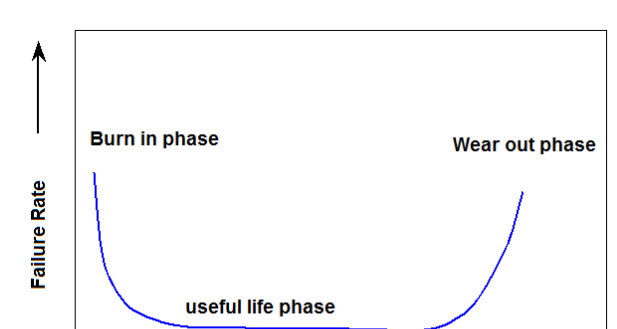
MTBF can also be expressed as MTBF = 1 / failure rate It is important to differentiate between MTBF and service life of power electronic equipment. MTBF is to be used as a measure of failure rate during useful life phase only.Mean Time Between Failure (MTBF) is not the same as the operational life of a product. In fact,MTBF represents the statistical approxim ation of the percentage of units that will pass during aproducts useful life period.
The most important reliability concepts that have evolved over time are those based on study of Physics of Failures.This requires multidisciplinary approach armed with knowledge in basic sciences such as materials science, heat transfer, electromagnetic theory, structural engineering & mechanics and probability theory.Over the past two decades the application of Finite Element Methods has become popular and helps to provide a much better understanding of reliability based on Physics of Failures Design engineers can create virtual prototypes of power electronics systems and then use software to predict failure mechanisms, based on physics of failure, using finite element methods and taking into account physical properties of various materials used, applied stress and thermal properties to guide them before undertaking actual manufa cturing.
Accelerated stress screening, accelerated life testing and environmental stress testing will help find out quality issues of finished power electronic products and, by correcting these,higher reliability can be achieved.To find out about infant mortality, Highly Accelerated Life Tests are designed to suit the power electronics sub systems. This can combine thermal cycling and random vibrations.While the temperature ramps up and down between 550C to+1250C, linear and rotary vibrations are applied to test bed in six axes. The rate of change of temperature and dwell times and amplitude and frequency of vibrations should stay within designed limits.
1.3Failure Mechanisms Due to Stress and WearOut:
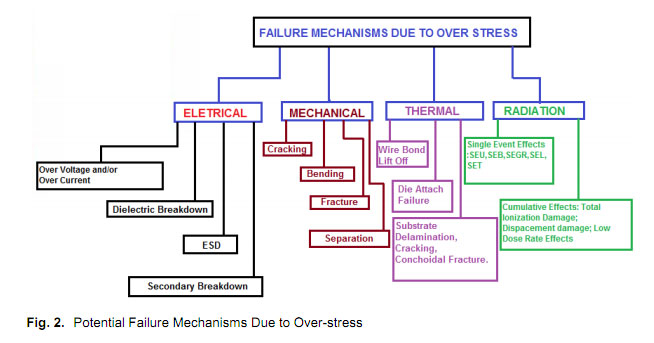
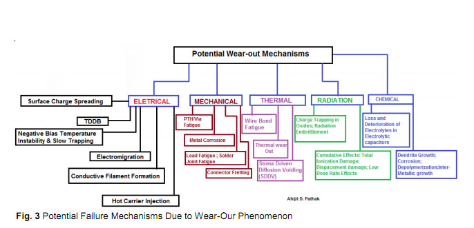
The potential or likely failure mechanisms of power electronic components, modules or systems have many facets and likely causes & effects.These are shown in Fig. (2) and Fig. (3).
A less likely but lethal electrical stress could be lightening. Very special provisions have to be made to prevent any damage to power electronics from lightening. Amongst the mechanical stresses, shock and vibrations can cause damage and Power Electronic system has to be designed with suitable protection.
2.0 Recommended Practices for Ensuring Reliability of Power Electronics:
2.1 Methodical Steps from Design to Installation:
1.Prepare most comprehensive design process,taking into considerations all margins,following fail safe methodology and required redundancy.
2.Choice of reliable components and parts.Keep in mind the wear out mechanisms of each part.Use minimum components.Making a simpler design helps attain higher reliability.
3.Use of established manufacturing processes followed by quality assurance& inspection at each stage.
4.Study of the environment and worst case operational conditions envisaged and translate this in to adapting or changing the first three steps above.
5.Incorporate EMI protection by incorporating EMI/RFI filters and other mitigation schemes.
6.Testing the finished product thoroughly against all specifications in simulated environments.
7.Ensure that the manufactured power electronics product is safely transported and correctly commissioned.
8.Make sure that the concerned users are well educated about correct application aspects,ensuring no out of bound stresses are applied during the life of the product.
2.2Typical Stress and Thermal Analysis and Safe Operating Area:
As an example of analysis recommended for determining stress and thermal margins, following table in Fig.(4) provides typical stress analysis and thermal analysis data of just a few components.
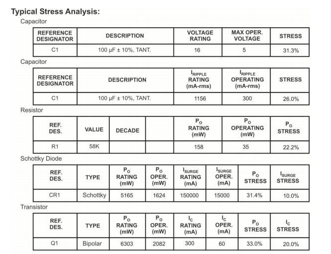
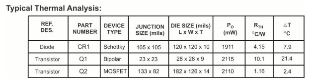
Fig.(4) Stress and Thermal Analysis of few components of a Power Supply
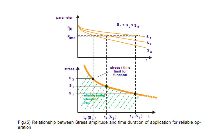
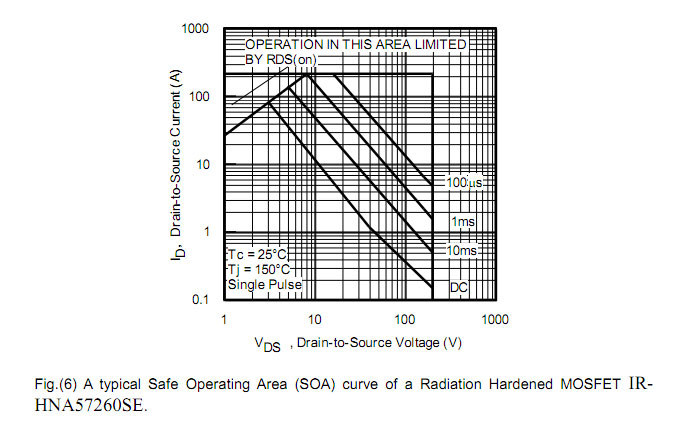
In Fig.(5) general concept of safe operating area, explaining relationship between stress amplitude and time duration of application for any parameter is explained. As an example SOA graph of a radiation hardened MOSFET is shown in Fig.(6). In both the figures, left lower corner of the graph shows Safe Operating Area and restricting operation within this region ensures higher reliability of power electronics components or systems.
2.3 Other Analytical Methods:
PFMECA Process Failure Modes Effects and Criticality Analysis dvantageously used to identify potential failures in a power electronics manufacturing process,rank the criticality of the failure types and to identify actions required fomitigating failures. The main use for PFMECA is for early identification of potential failure modes so that one caneliminate or minimize them quickly.
TheFMECA (Failure Mode & Effects Criticality Analysis) of power electronic system is a detailed quantitative work. It lists function performed by each constituent component, explores all probable failure modes, gives failure rates,provides information about effects and determines criticality of every likely failure.
Worst Case Analysis (WCA) takes into account the worst operating conditions and End of Life behaviour of all components and sub systems of power electronics and provides various data on specifications of interest for manufacturer and user. As an example for the control loops of power electronics, computed and measured phase margin and gain margin under worst case conditions should ensure unconditional stability.Likewise computed junction temperatures of all power semiconductor devices should be well within limits under worst case operating conditions & environments.As another example,For a DC to DC Converter operating aboard a satellite,a Worst Case Analysis (WCA) can confirm that its voltage regulation, ripple, efficiency,Phase and Gain margins should all be well within specified limits at End of Life under worst case conditions.
Other simulation software solutions allow design engineers to create virtual prototypes of power electronic systems so that they can predict how such complex power electronics product will behave under actual operating conditions. This guides design engineers to tweak their designs and rerun the software to arrive at final design.
3.0Designing Methods & Processes and Selecting Standards for Different Applications to Achieve Highest Reliability
3.1Space Applications:
Of all applications of power electronics, its use in space calls for ultimate reliability.Reasons for this are:
1.The power electronic subsystems can not be repaired in space.
2.The cost, objectives & time required for lfunction in any sub system or component as it could jeopardize wholly or partially the mission objectives.
3.Space environment is unique with radiation, absence of atmosphere and gravity, making it necessary to use radiation hardened components and dissipate heat by conduction and radiation only.
4.Weight, volume and power are costliest in space and hence maximum efficiency in smallest volume and weight are to be achieved with highest reliability and longest life.
5.Power electronic sub systems should feature remote operation throught elecommand and performance monitoring through telemetry, justifying need for special reliability measures.
Screening, testing and inspection requirements for power semiconductors for space applications are done as per MIL PRF 19500.MOSFETs,Schottkys and Solid State Relays required for building power electronic subsystems should be radiation hardened.Likewise, the power management ICs and other ICs,should be radiation hardened by design with required redundancy.All DC to DC Converters and Motion Control Products should be radiation hardened.Immunity towards Total Ionization Dose (TID) and Single Event Effects (SEE), is a must for ensuring reliable operation for all the above. SEE includes all its variants such as SEU, SEB,SEGR, SEL,SET. Level of radiation hardness required depends upon type of orbits.In addition, one has to test for ELDRS, Neutron effects and displacement damage in certain cases.
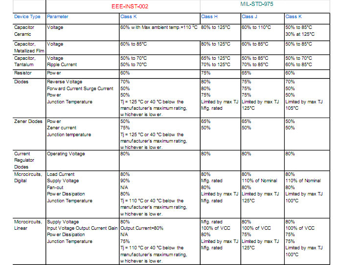
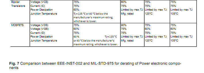
MIL STD 1547 is for electronic part, materials and processes for space and launch vehicles.NASA has produced EEEINST 002, which contains Instructions for Electrical, Electronic &Electromagnetic Parts Selection, Screening, Qualification and Derating.A comparison between EEEINST 002 and MIL STD 975 for derating of many power electroni c components was done and is shown in Fig. (7). MIL STD 750/5 is for High reliability space application test methods for semiconductor devices. When the relevant standards are followed,it helps towards achieving compliance and reliability.EMI compliance is done as per MIL STD 461 to ensure reliable operation.
3.2 Military and Aviation Applications:
Power electronics built for military and aerospace fields have different requirements, as the operating environment and application aspects are different. MILSTD 810G describes test methods and environmental aspects for this application.This can involvetests in presence of ck & vibrations,thermal cycling and corrosive atmosphere such as salt spray and fog.Other environmental tests are done as per application requirements.For checking reliability,accelerated stress screening, accelerated life testing and environmental stress testing are used. Tests are performed to verify compliance with EMI standards:MIL-STD 461, MIL STD 1275 and MilSTD 704.
As the world moves from "More Electric"to "All Electric" Air crafts accent is on lighter d reliable power electronic components and subsystems.Removing hydraulic systems with power electronics improves aircraft reliability and reduces complexity, weight, installation, maintenance & replacement and running cost.Air craft designers are demanding much more power processing from smaller and lighter components.
Power electronics are designed into a wide variety of military and commercial aircraft for applications such as cockpit electronics, radar, electronic warfare systems, signal conditioning of sensors, wiper motor controls, automatic test equipment, displays, computers, in flight entertainment systems and in galleys for food preparation.Use of DSPs and microcontrollers help in developing software based controls,which can be adapted, modified or improved at will.These DSPs and Microcontrollers use Point of Load converters,which need to be highly efficient and reliable, to supply low voltage with high current at high di/dt.
Modularization and standardization of power electronics for air crafts is desirable. Achieving reliability of power electronics for air crafts is an equally challenging field. Location of power supply or DC to DC Converter should be optimized to reduce wiring length between power and load. At the same time, one understands that in wing or belly fairing areas and in many other parts of air craft,power electronics systems have to face environmental hazards.Installing power electronics systems in locations with pressurized air help its operational reliability.Commercial and Military Aviation are fields,where in human safety are of paramount importance and hence reliability of power electronic systems have to be treated with special care and attention.
4.0.Conclusion:Power Electronics has progressively gained important status in the realm of engineering and in modern day living. Now nearly 70%of all electrical energy, from Watts to Megawatts, is processed through power electronics. This is likely to go to 80% in 2015. Hence achieving reliability of power electronics becomes all the more necessary, while optimizing its design and manufacturing with highest efficiency in smallest volume.Power electronics form scritical segment of many HiRel applications, making it all the more necessary to achieve highest reliability during long life, without requiring any maintenance or repair.
Principles of reliability practices are more or less universal and also applicable to both power electronics components and systems. Deeper understanding of the physical processes in volved coupled with modern simulation software enable more reliable design and manufacturing methods. Accelerated testing in simulated environment,while using thermal cycling coupled with shock &vibrations have benefitted detection of early failures. Greater understanding of various wear out mechanisms has helped in taking necessary precautions and maintaining safety margins.
Applications of power electronics in space require attention to radiation hardness, heat dissipation in vacuum, absence of gravity and adherence to many quality standards established.Likewise applications in military and aviation also demand high reliability and long life but have different standards, environment and requirements to comply with.
Power electronic systems use more and more of digital controls using DSPs, FPGAs and microcontrollers. I hasten to add here that the total reliability of such a power electronic system has to take into account integrity of the hardware and software of such digital platforms. This is because "a chain is only as strong as it is weakest link.
The observed trend is healthy and more and more manufacturers are following many of the required steps and recommendations to ensure that power electronic components and systems continue to be more reliable and long lasting.
5.References:
1.Joseph B. Bernstein,Moshe Gurfinkel, Xiaojun Li, Jrg Walters,Yoram Shapira, Michael Talmor:Electronic circuit reliability modeling,Microelectronics Reliability 46 (2006) 1957 1979
2.MIL HDBK 217: Reliability Prediction of Electronic Equipment
3.National Aeronautics and Space Administration EEE INST 002: Instructions for EEE Parts Selection,Screening, Qualification,and Derating
4.MILSTD 975 :NASA standard electrical, electronic, and electromechanical (eee) parts list
5.Peter Hansen: Physics of Failure, power Module and Thermal Design
6.Stress Analysis and Thermal Analysis of Hybrid DC to DC Converters: International Rectifier,HiRel Business Unit, San Jose, CA , U.S.A.
7.ECPE Tutorial : Reliability of Power Electronics Systems, Prague,July 22 23,2009,Page:17
8.A.AAbdElhafez,A.J.Forsyth:"A.j.Forsyth:"A More Electric Air craft:13th international Conference on Aerospace Sciences & Aviation Technology,ASAT-13,May 26-28,2009.